
For my main project, I decided to build front suspension uprights for my 1965 Ford Mustang race car project. This race car must comply with a strict set of rules within the GT1 TransAm section of the Sports Car Club of America General Competition Rulebook in order to be allowed to race in my desired class. In order to be a competitive vehicle, I decided to design a complete custom chassis and suspension that optimize the rules to create to fastest possible car. As a result, the original front suspension and uprights for this vehicle were no longer useful and I decided to design my own uprights which optimize the suspension geometry and allow me to run any combination of brake system and wheel hubs that I chose to be the best for my application.
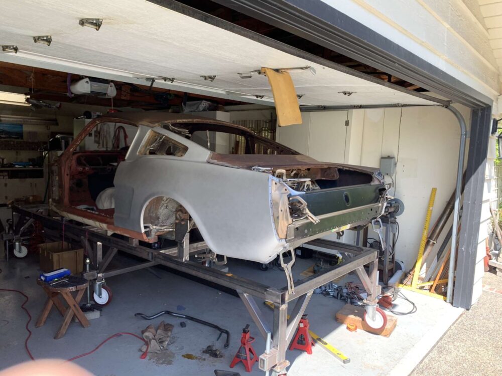
The figure shown below is an image of my 1965 Ford Mustang shell that has been fixtured to a chassis table. The chassis table allows for the car to be held securely in place while the chassis table is used as a reference datum to build out the suspension of the vehicle.
Before moving forward with my design process, I focused on defining an aesthetic for the project and decided that an aerospace aesthetic would be the most appropriate. I chose this aerospace aesthetic as I found it the most fitting for a race car, with the overall goal of the design being lightweight and highly rigid to outperform the competition. The aerospace aesthetic consists of geometric patterns such as grids and triangles which are quite appealing to the viewer and serves a functional purpose of removing weight from a component while maintaining the strength. These features are often associated with the design of structural members of airplanes and spacecraft. This aesthetic also showcases streamlined shapes and smooth radiused edges that reduces the amount of stress risers on a surface in which a crack could propagate and lead to a failure. Additionally, the chosen materials in that make up this aesthetic are often state of the art, such as high strength metals and composites, which allow for high strength and low overall weight of the designs.
The next step in my design process was to define some parameters around my design such as the geometry of the upper and lower control arm attachment points on the upright as well as the vehicle scrub radius and kingpin inclination angle. For my design, I am utilizing a 12-inch wide by 16-inch diameter front wheel and decided to make sure that my control arm pivot points were as close to the inside of the rim of the wheel as possible to reduce stress on the suspension components. Next, I decided that I would use a HOWE style 5×5 wheel hub with a 2-inch spindle bearing as this is a very standardized front hub design that has been tried and tested for years on many NASCAR teams and is supported widely by many different manufacturers. With the front hub chosen, I was able to locate the wheel hub as close as possible to the lower control arm attachment point and minimize the scrub radius to reduce jacking forces on the tire during turning of the vehicle.
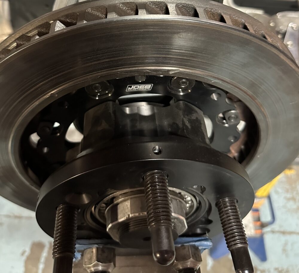
The figure shown below illustrates a 5×5 wheel hub produced by Joes Racing Products with the rotor mounting flange and a Wilwood brake rotor attached.
One of the main goals of my design was to maximize adjustability of my suspension geometry and focus specifically on the caster trail adjustment. Caster trail is a very important aspect of a vehicle’s front suspension that directly affects the steering stability and the responsiveness of the car to steering inputs. The caster trail can be adjusted by moving the front axle centerline away from the centerline of the kingpin. I decided that the best way to create this adjustment was to design a set of removable keys which insert into the upright body and capture the bearing pin. Switching out the set of keys for different offsets would allow for the bearing pin to be moved forward at different offsets from the centerline of the kingpin.
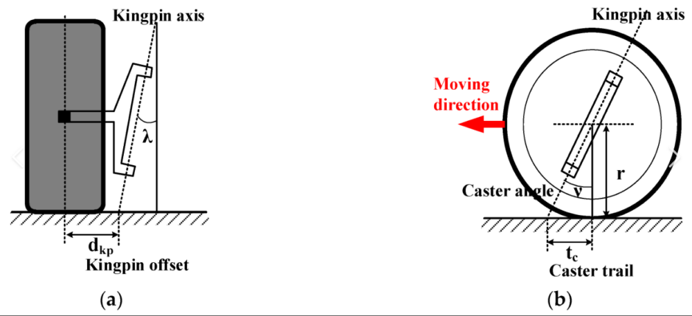
The figure shown below illustrates the vehicle scrub radius (dkp) on the left which is the distance between the center of the tire contact patch and the point where the kingpin axis touches the ground. This value can be manipulated by changing the geometry of the upright and the offset of the wheel hub mounting flange. The image on the right shows the caster trail value (tc) which is the distance between the centerline of the spindle and the contact point of the kingpin axis on the ground.
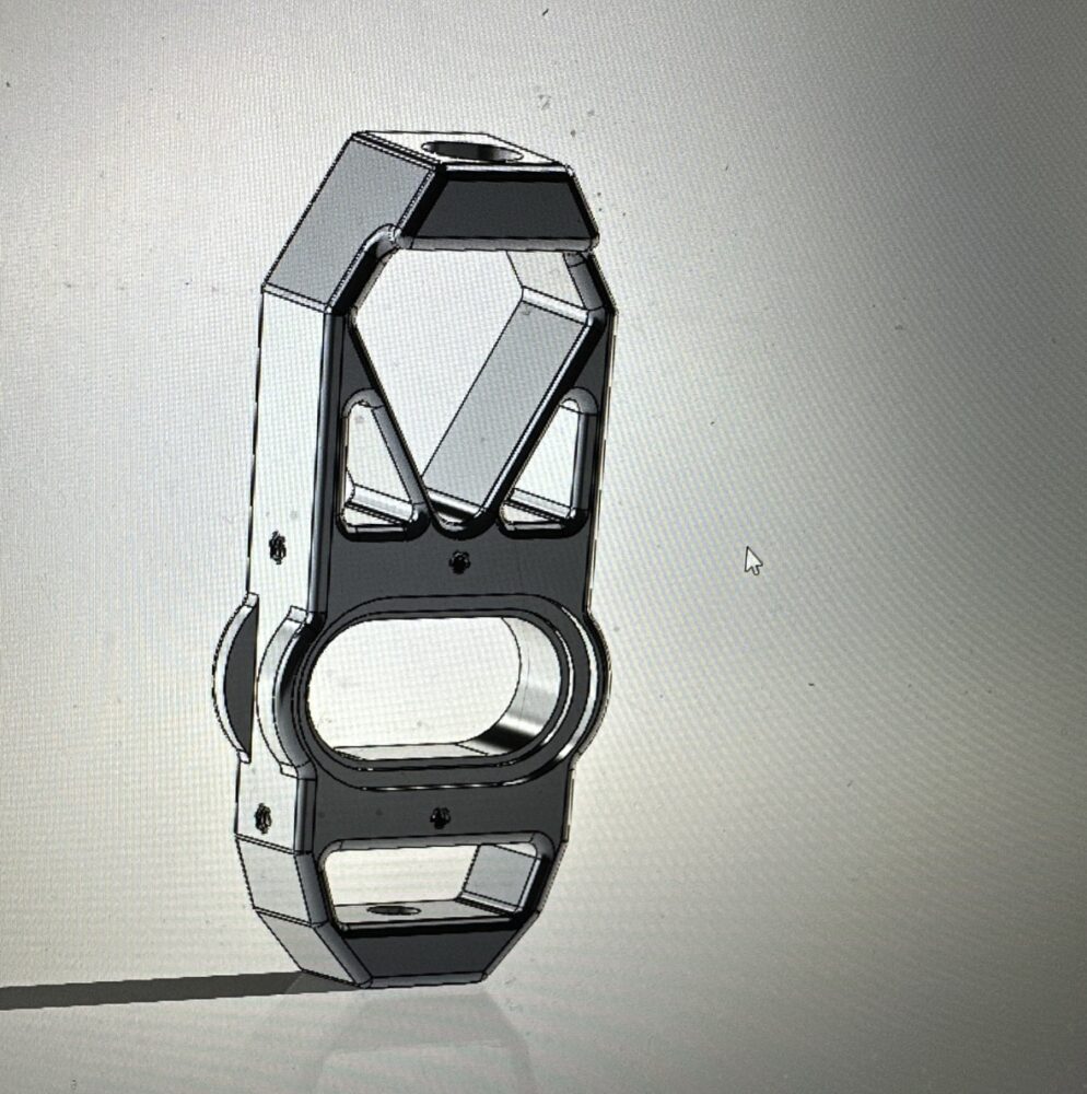
After defining the parameters that surrounded my design, I decided to begin using SolidWorks to develop an initial design and refine it to my needs. The figure below illustrates my first iteration of the upright design which includes a mono ball spherical bearing pressed into the upright as my upper control arm attachment. The ball joint of the lower control arm will be external to the spindle and mounted in the control arm itself. This design utilizes a separate brake caliper mounting bracket and steering arm that bolts to the side of the upright. The upright is symmetrical so that it can be a universal fitment on both the right and left-hand sides of the car. Therefore, I require fewer spare parts on hand at competition if an upright does fail.
As I refined my design further, I came up with the idea that I could remove the additional brake caliper mounting bracket if I secured the brake caliper in place with T-nuts. The use of T-nuts allows for adjustment in the offset of the caliper which would traditionally be controlled using shims between the interfaces of components. As the brake pads and rotors wear from use, I will easily be able to adjust the caliper placement using these T-nuts.
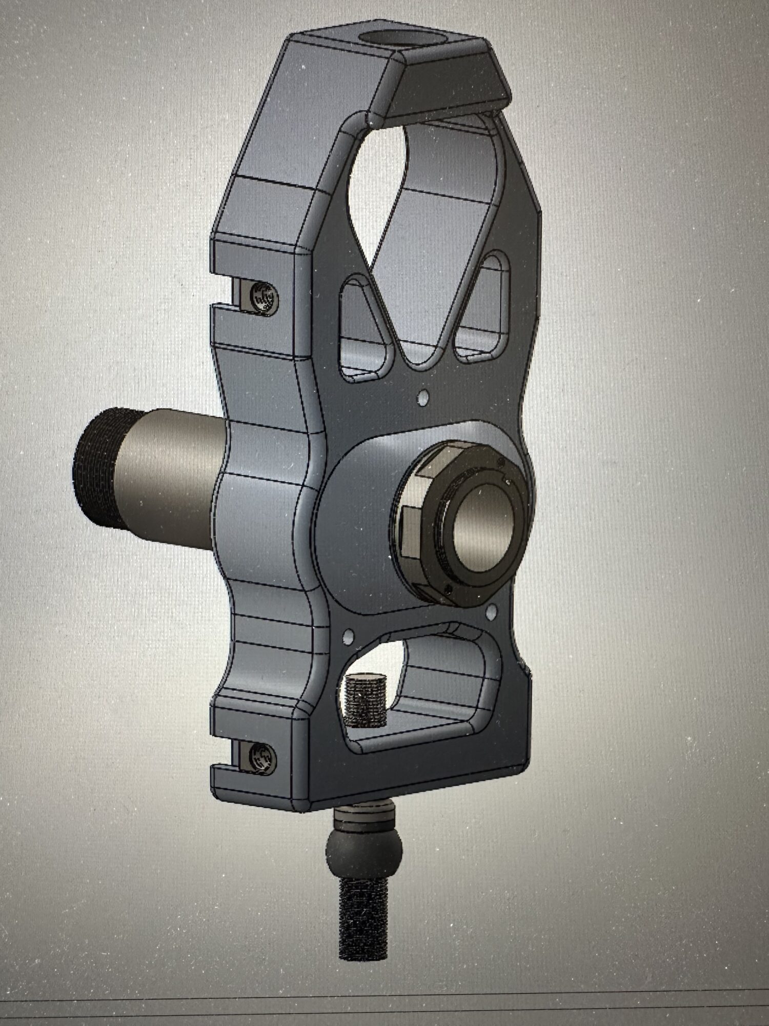
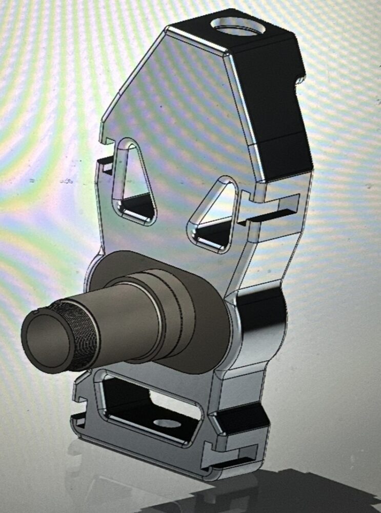
The figure shown below illustrates the modified design of the upright using T-nut slots as mounting points for the Wilwood brake caliper and custom steering arm. This image also illustrates the fully designed spindle bearing pin with the centered caster trail adjustment keys.
Moving forward to the next step of the design process, I wanted to stay on path with the aerospace aesthetic and make the upright as light weight as possible while maintaining strength. In order to achieve this, I decided that the most appropriate material to manufacture the upright body and adjustment keys would be 7075-T651 aluminum due to its lightweight and high strength properties. However, the bearing pin would ideally be manufactured from 4140 chromoly steel due to the higher bending stresses on this part of the design caused by high braking and cornering forces.
After performing hand calculations and Finite Element Analysis on the model, I discovered that the use of these high strength materials would allow me to pocket out the upright body further without compromising the durability. As a result, I was able to remove more weight to create a design with a standard safety factor of 1.5 which is common to race car and aircraft design.
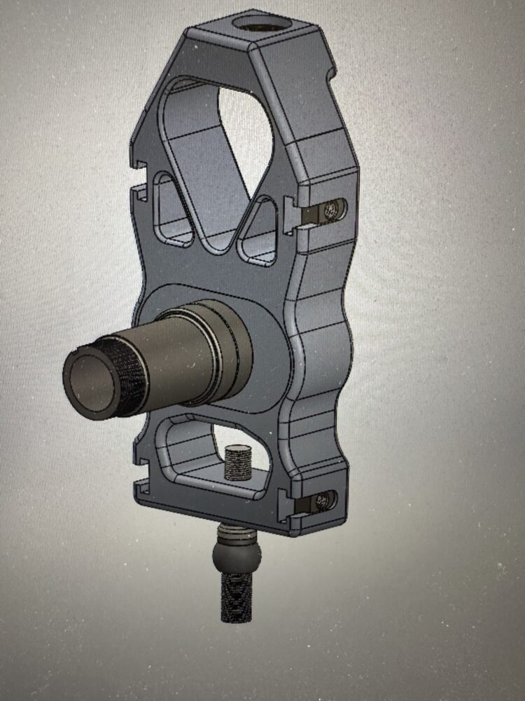
The figure shown below illustrates my finalized design that is ready to be manufactured. The final iteration of this model features more pocketing of the billet aluminum to reduce weight as well as fillets and radiused edges which are make for a more easily machinable design using 3 axes milling technologies.
In order to manufacture this upright, I have decided to use a couple of machining methods on the various components. I will primarily be using a manual lathe to manufacture the bearing spindle. However, the upright body and adjustment keys will need to be manufactured using a 3 axes CNC milling machine. In order to stay within a reasonable budget, I am going to use a Haas CNC milling machine owned by a close friend to manufacture these complex components as outsourcing to largescale companies would be incredibly costly. At the moment, I have already ordered all of the necessary 7075-T651 and 4140 stock materials to machine these components and am currently waiting to receive the materials.
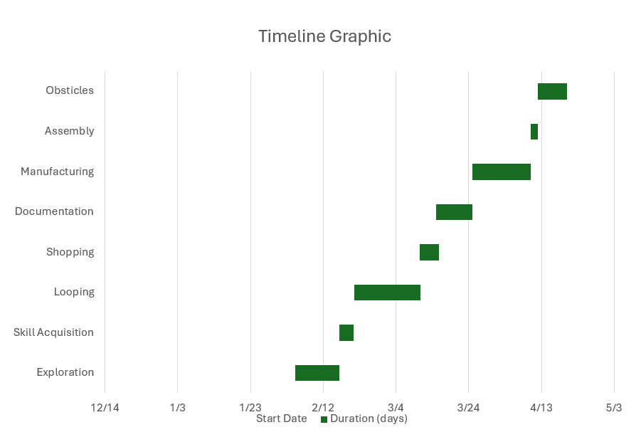
This figure shown below illustrates the approximate timeline that I have in order to complete the project. This timeline includes previous components of the project that I have already completed including all of the exploration, skill acquisition, looping, and shopping for materials. At the moment, I am still in the process of documenting all of my machining tolerances to make sure that all of the components easily assemble together. The next step of this process is manufacturing which can begin as soon as materials have been received and the Mastercam program has been completed to machine the components. I have allocated a short window of time to allow for assembly of the spindle that is followed by a longer timeslot to allow for the solving of any obstacles that may take place in the upcoming weeks. These obstacles can include manufacturing challenges or assembly issues which may delay the completion of the project.
Sources:
Kim, Seong Han, and Min Chul Shin. “Steering Pull Model and Its Sensitivity Analysis.” MDPI, Multidisciplinary Digital Publishing Institute, 14 Nov. 2020, www.mdpi.com/2076-3417/10/22/8072.
2 Comments. Leave new
This is an impressive and well-thought-out design process. The focus on optimizing suspension geometry and maximizing adjustability really shows a deep understanding of performance engineering. The aerospace aesthetic is a unique touch that not only adds to the design visually but also enhances the functionality with its focus on strength and weight reduction.
I’m curious, how are you planning to test the adjustability and strength of the uprights once they’re manufactured? Will you be doing track testing, simulations, or both? Excited to see where this ends up!
Hello Jacob, thank you for the comments. I also thought that the aerospace aesthetic would fit well with improving the functionality of the design. I plan to do some static testing on scales to see how to caster trail adjustment will affect the dynamic cross weight of the vehicle. I then plan to do some track testing as I have already run suspension simulations on this model. Thanks for all of the feedback!