LED Lights
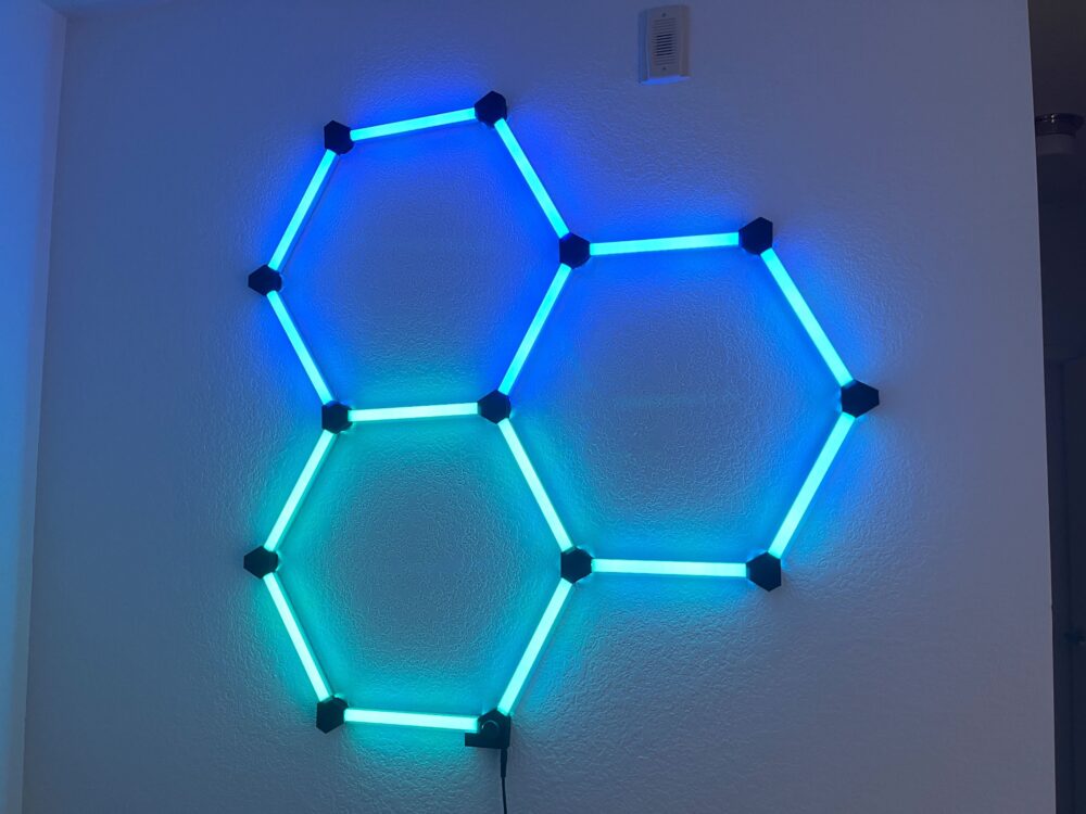
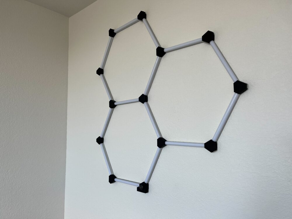
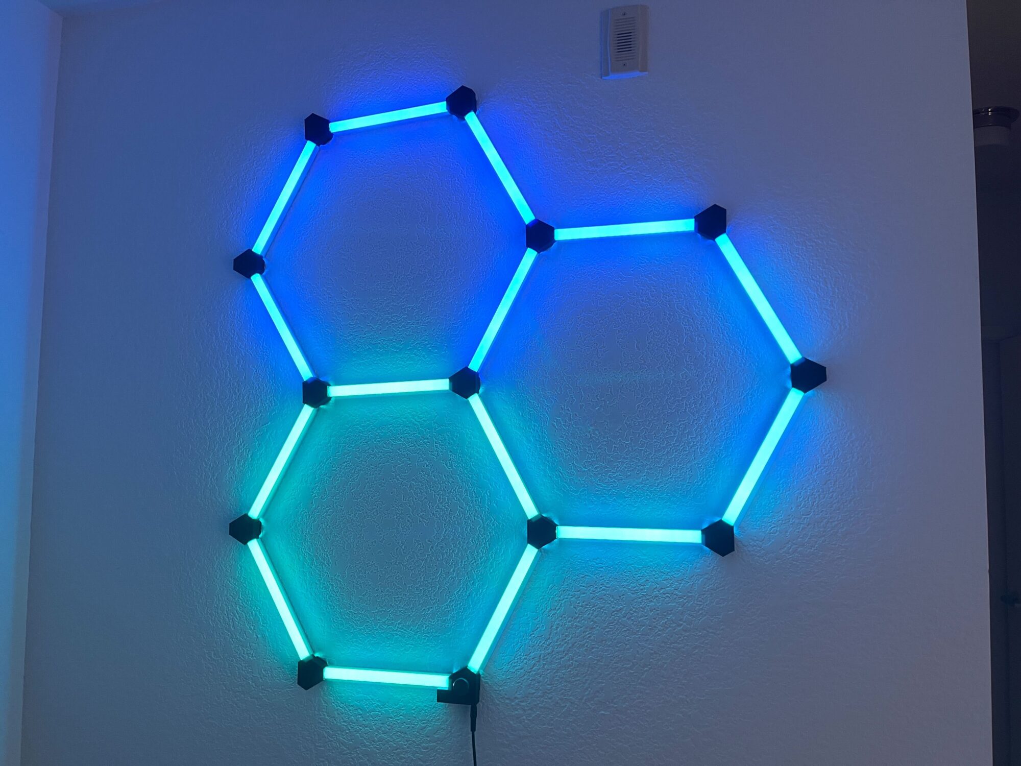
For my project, I made these RGB LED lights for my room. It consists of a controller board at the bottom, LED segments, and nodes. The nodes are the black spots that connect everything together and the segments contain the LEDs. There is a rotating knob at the bottom with a pushbutton that controls brightness.
Early Testing
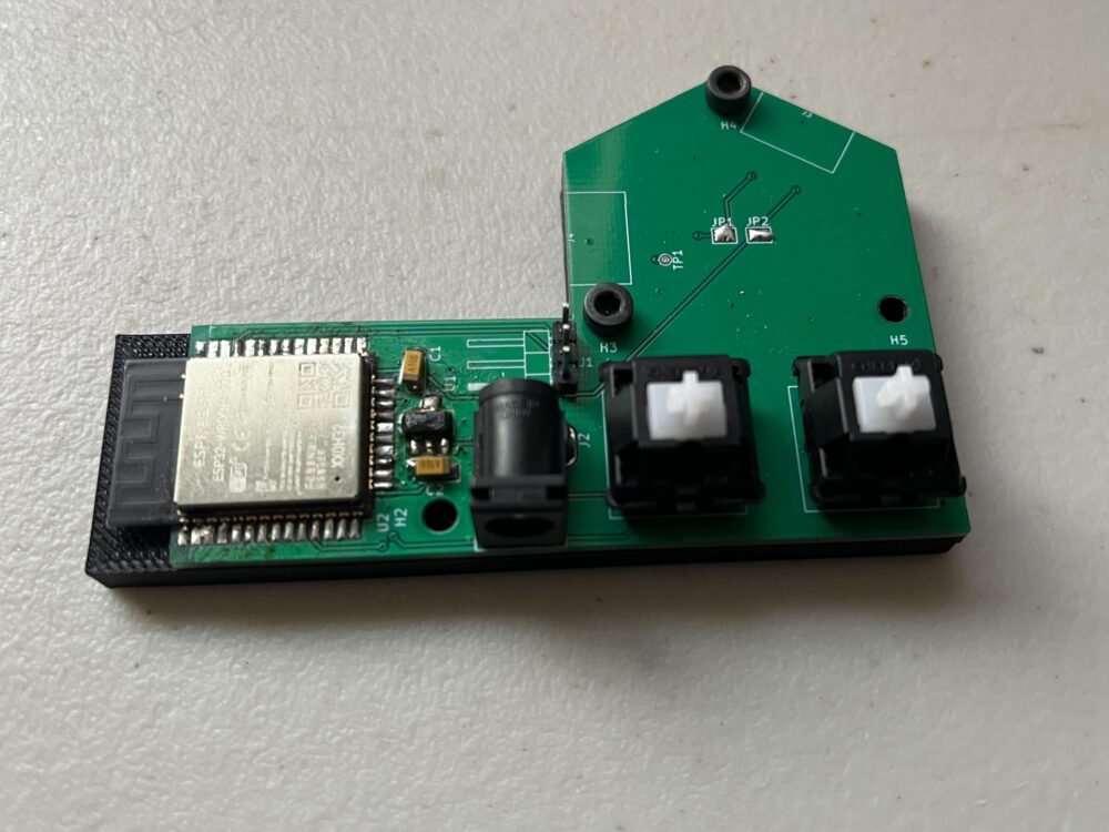
Early on, I wanted to try a custom controller instead of using an off-the-shelf Arduino. This early model uses an ESP32, a linear regulator, and Cherry MX red key switches. I learned that this version was difficult to program since it didn’t have a USB port, reset switch, or boot mode switch. I also learned that the key switches are not intuitive to use and are spaced wrong.
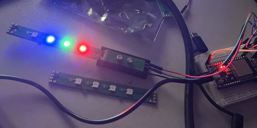
I also did some testing with small versions of the LED strips to make sure I could connect to and control them.
The Design
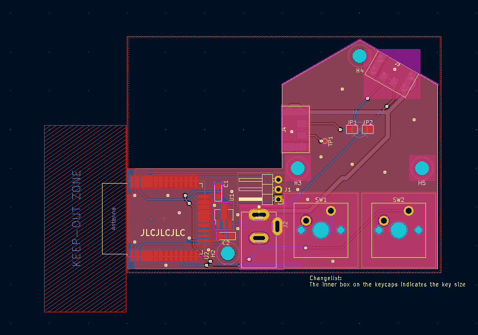
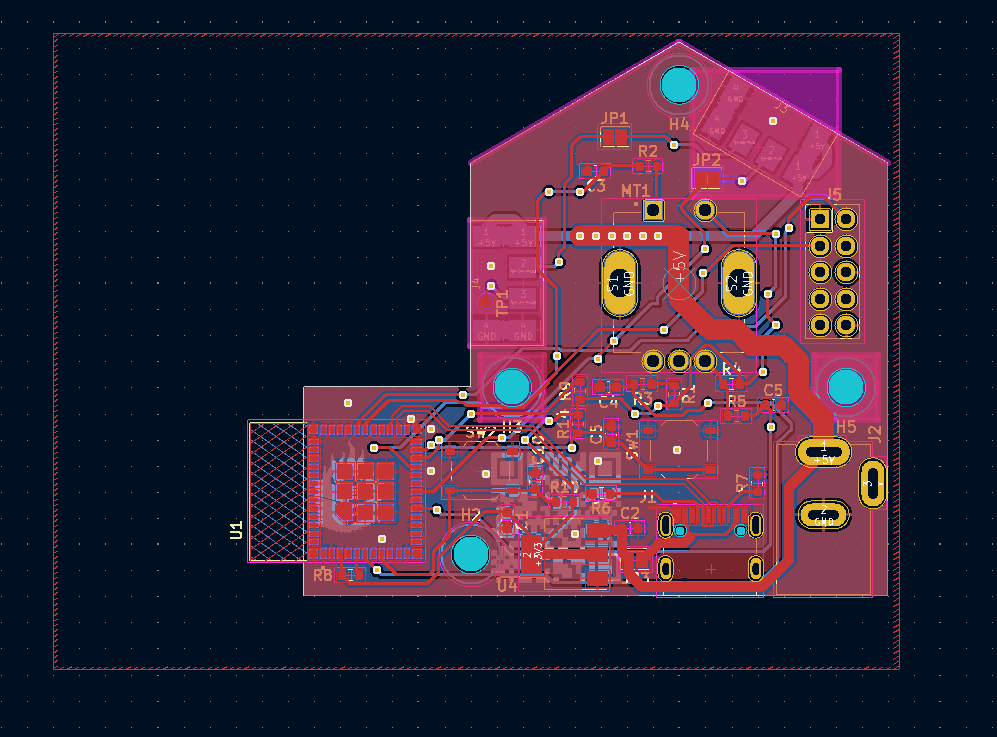
The art piece was designed in Solidworks and Ki CAD.
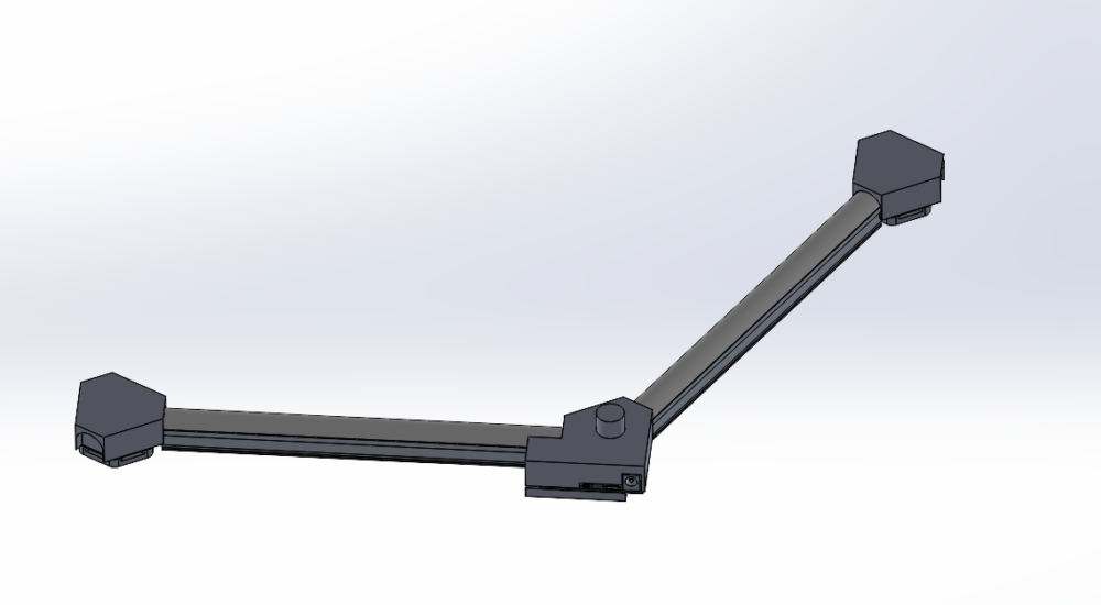
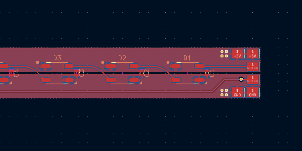
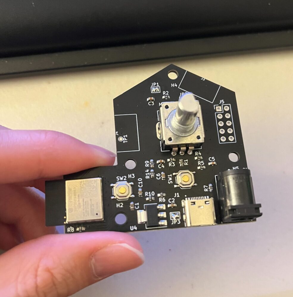
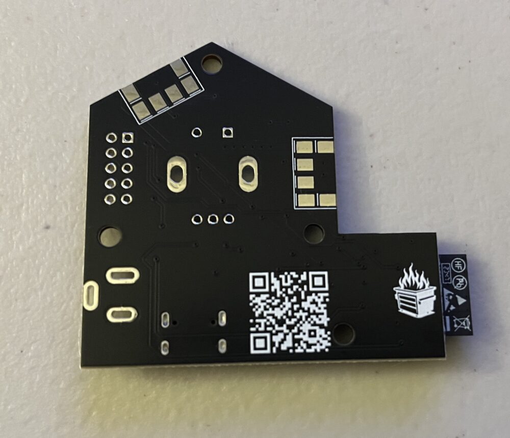
Next, I designed a new controller board. This one now has USBC, a pushbutton knob, a newer chip, and a smaller form factor. This uses the ESP32-C3 which is a newer and smaller version of the ESP32.
The Build
Node Assembly
Segment Construction
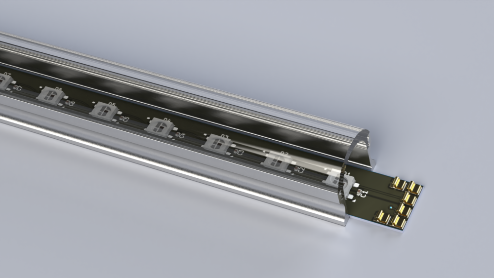
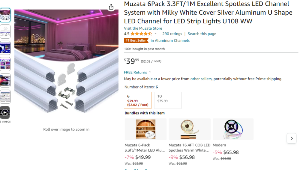
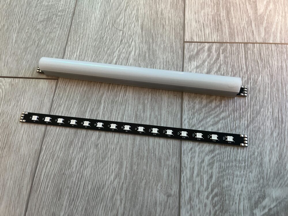
The LED segments were constructed by inserting the LED strips into the LED diffusers. First, the LED diffusers were cut to length using a bandsaw and then double-stick tape was used to fasten them together.
Once the segments and nodes were assembled, I arranged everything on a wall, inserted the LED segments into the nodes, and fastened everything using 3M Command.
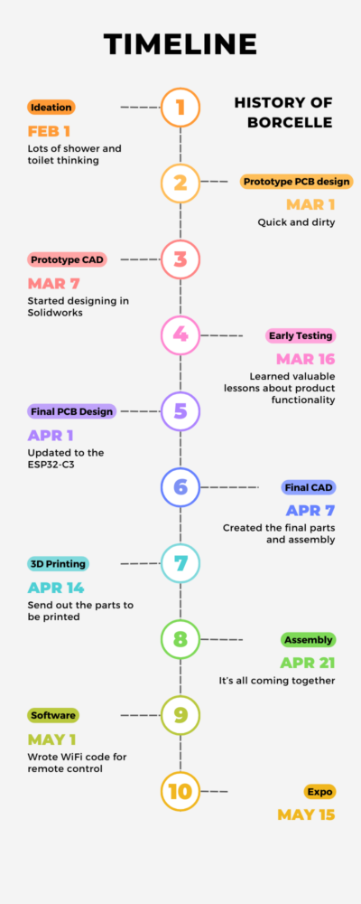
Timeline
Sources
https://nanoleaf.me/en-US/products/nanoleaf-lines/?category=lines-60-degrees&pack=smarter-kit&size=9

1 Comment. Leave new
I’m very impressed by the quality of your work here, it seems like something you put a lot of time and effort into. It looks almost professional, or like something bought off the shelf. If you were to do it again with the knowledge you’ve gained, what would you change?