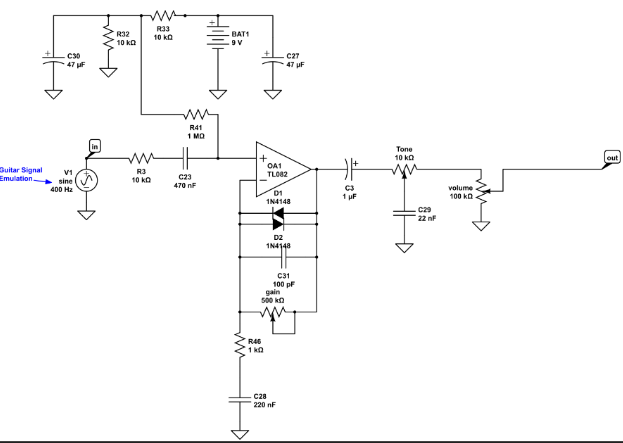
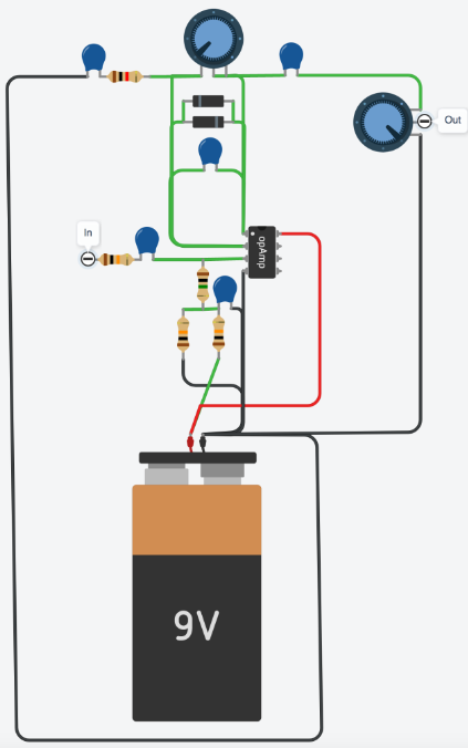
My main reasoning for building an overdrive guitar pedal was because I didn’t have any and off the shelf pedals are fairly expensive. With enough research online and through YouTube, I figured that I would be able to create a circuit that functions as an overdrive in a guitar pedal configuration. For this pedal I have several inspirations. The first inspiration has to do with the functionality of the circuit. While looking online, I found a website called Wampler pedals that is a business that makes various guitar pedals. They had a video/blog that talked about the circuit design of an overdrive pedal and how to build it, as well as add more functionality into the pedal in various steps.
 [2]
[2] [2]
[2]
Using the schematic provided on their website, I ordered components that were used in the overdrive pedal on the blog. However, after watching the video, I found a few glaring issues with the way Wampler pedals set up their circuit that I wanted to change. First, one of their capacitors they used in their circuit I was unable to order. After looking into how the circuits work, I determined that the remaining circuit would work fine as even if this capacitor wasn’t included. I also took out two diodes that Wampler used as I could not figure out how to make them work. Even with the circuit edits, my circuit was still playing an overdrive tone. I also made the discovery that the Wampler circuit had no footswitch wired in to act as a bypass. This essentially means that when the guitar pedal is plugged in, the only sound that can be heard is an overdrive tone and the pedal can not be switched to clean guitar tone. To fix this issue, I did some self research and tested LED routes on a breadboard to see how a footswitch works. After determining how the switch works, I used some simple circuit assumptions to figure out that the switch would let signal through some parts of the circuit and not others. When configured correctly, my bypass switch ended up working very well.

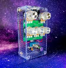
My other visions for the project came in the casing that was going to be used to contain the circuit. My initial idea was to make a clear polycarbonate casing that would have a transparent aesthetic showing the electronics.
 [1]
[1]
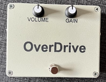
However, after talking to a guitar pedal hobbyist, he said to not do this as the polycarbonate plastic might not hold under a person’s body weight when using the footswitch. Instead he recommended an aluminum box. I used the aluminum box and decided to switch to a minimalist aesthetic that uses metallic gray color with black and silver features such as the footswitch button, volume and gain knobs, and text. All in all, I mainly built this pedal for function as I wanted the overdrive tone to work. I also wanted it to have adjustable volume, gain, and an on/off feature which was implemented in the final circuit.

References:
[1]Cascade Pedals. “Hosstortion – Clear Acrylic Enclosure.” Cascade Pedals, cascadepedals.com/shop/ols/products/hosstortion-clear-acrylic-enclosure-built-to-orderpre-order. Accessed 1 May 2024.
Wampler, Brian. “How to Design a Basic Overdrive Pedal Circuit.” Wampler Pedals, 10 Jan. 2022, www.wamplerpedals.com/blog/uncategorized/2020/05/how-to-design-a-basic-overdrive-pedal-circuit/.

2 Comments. Leave new
Hi Ethan,
I’m really impressed by your work on editing and creating your own circuit! It sounds like it was a very involved process. I agree that using clear polycarbonate would have looked great, but I understand the limitations you face in your design. I’d love to know if you plan to change up the aesthetic design at all; I think some simple changes could make your design really stand out.
All the thought you put into the electronics is very impressive! I would be interested to hear how the overdrive sounds.