The progress that I have made on my final project is primarily in the virtual sense. I have already had the 1st iteration of my Strandbeest leg done. This iteration was creating simple leg segments and assembling them in SolidWorks in a 2D layout. This allowed me to see how the segments interact with each other and gave me a general idea of the size of the final product.
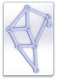
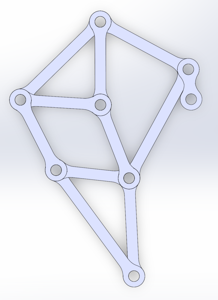
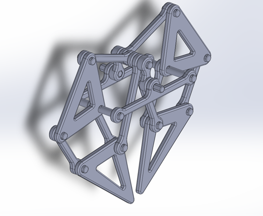
After the first iteration, I started working on the 2nd iteration. This one included adjusting the leg segments to a 3D layout and figuring out how the segments would interact and connect with each other. As shown by the figure below, I changed multiple separate leg segments into two triangles because these sections did not move or rotate after observing how the leg functions. Reducing the number of parts will make the final assembly easier.
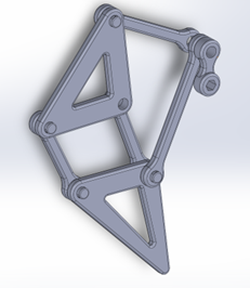
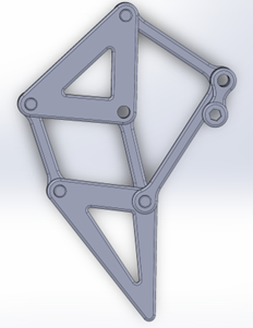
From the 2nd iteration, I was able to make a complete leg assembly, as shown in the image below. Next, I created the crankshaft that would power the entire Strandbeest assembly. This was done by creating hexagonal connector pieces. This will allow the Leg assemblies to be offset from each other by 120 degrees to enable the Strandbeest to walk.
The next step in my plan is to figure out how all the leg assemblies will be secured to each other. I am thinking of using long pins to go through the structure. Another step is to start test prints of the leg assemblies to determine the correct tolerances and ensure the connection points rotate properly.
