So, how I designed and manufactured the press?
After knowing what I wanted to end with, I began doing some research on the topic of Topology optimization and its typical workflow. So the typical workflow of this kind of studies (at least in Solidworks) is:
1- Modeling a “simple” geometry basically used to define the limits and key features of the final model. After having designed all the assembly, this was the result:
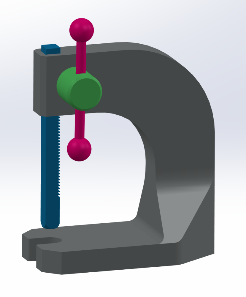
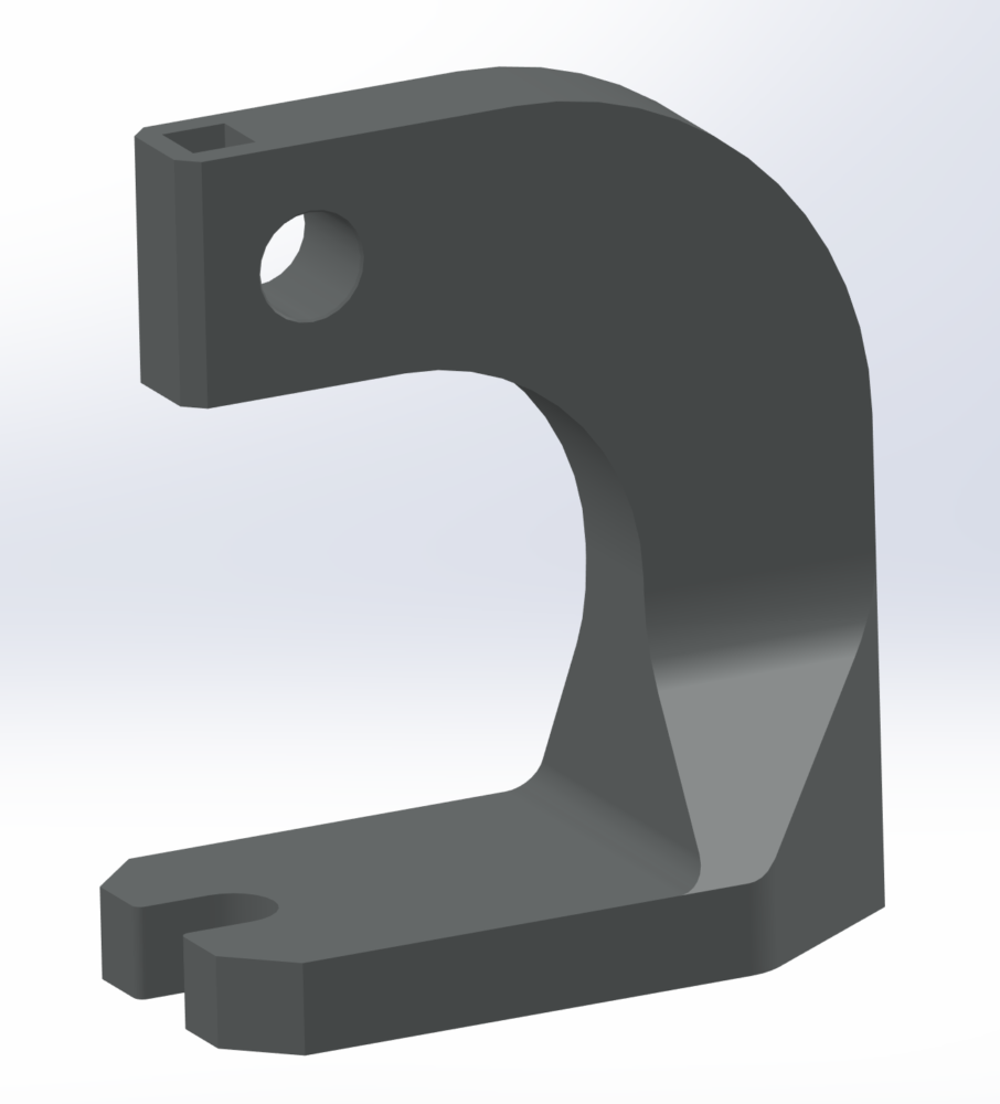
2- After that I had to check that the model was able to withstand without a sweat the stresses that I wanted the press to handle. If the “simple” geometry wasn’t able to withstand the stresses properly, there was no point moving forward with a study where one of the main objectives is to reduce mass. I ran a Static FEM study having the base as a fixed constrain and applying an arbitrary force of 5000N pointing up. For the final aesthetic look I wanted to obtain, I defined cast Iron as the material of the press.
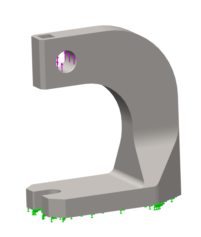
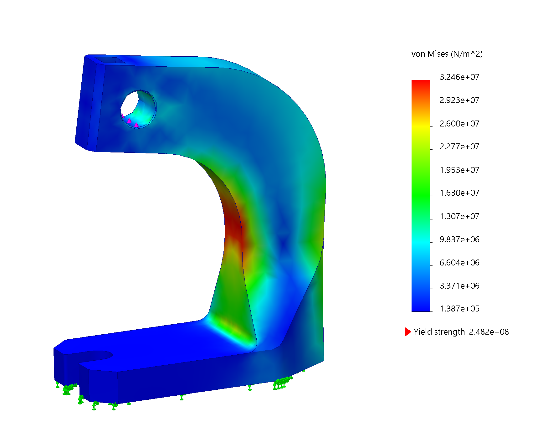
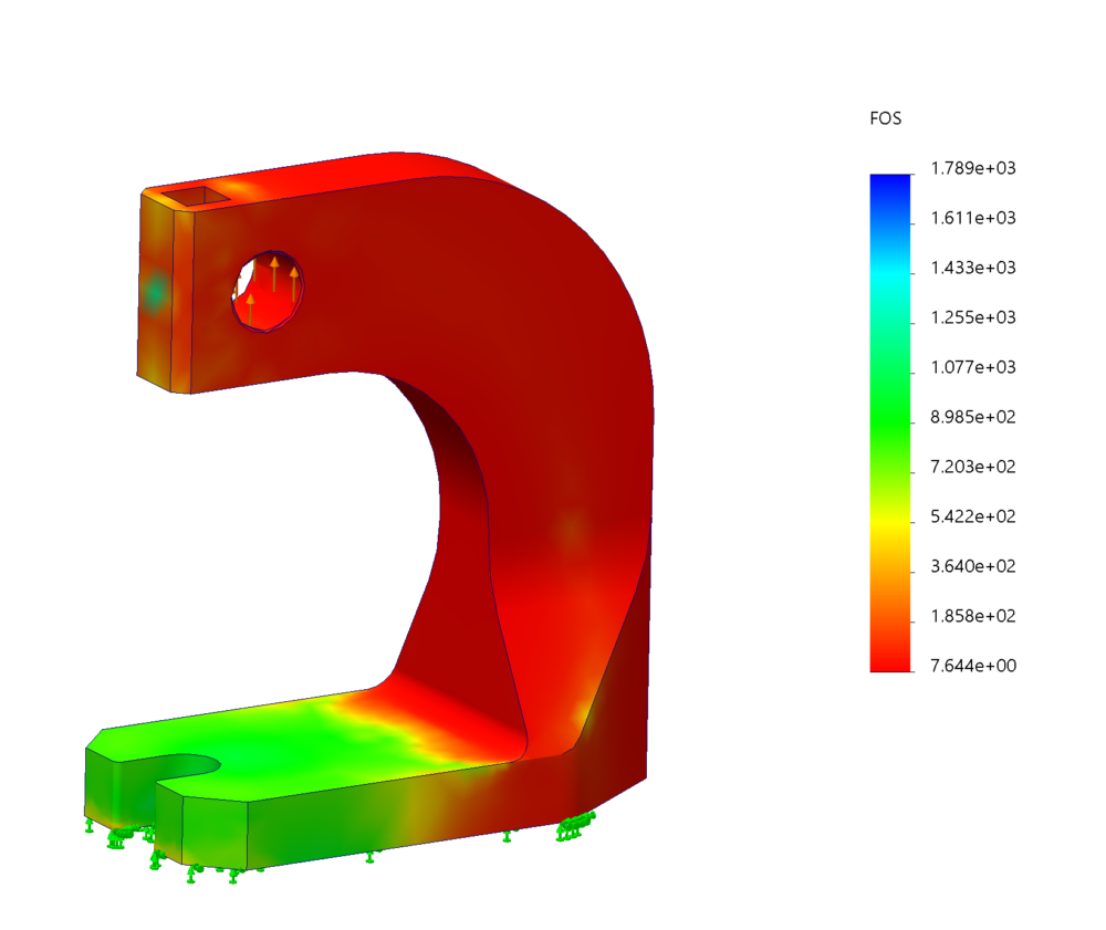
As we can see with the above images the minimum factor of safety that I had is 7.6, a lot, perfect for removing a lot of material. Actually I ended removing 75% of the material.
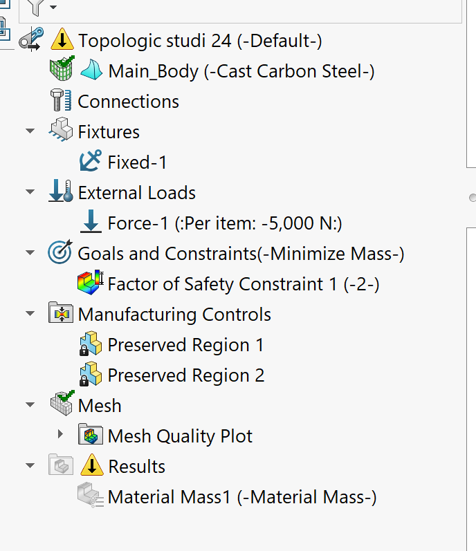
3- The third step consists in run the topology study. Copying the conditions and constraints of the static FEM study I applied the following constraints: The goal of the study was to remove as much material as I could while mantaining a Factor of safety of 2. Another constraints were made regarding keeping some specific features and surfaces (for example the base, the gear and rod enclosures, the pressing surface, etc.).
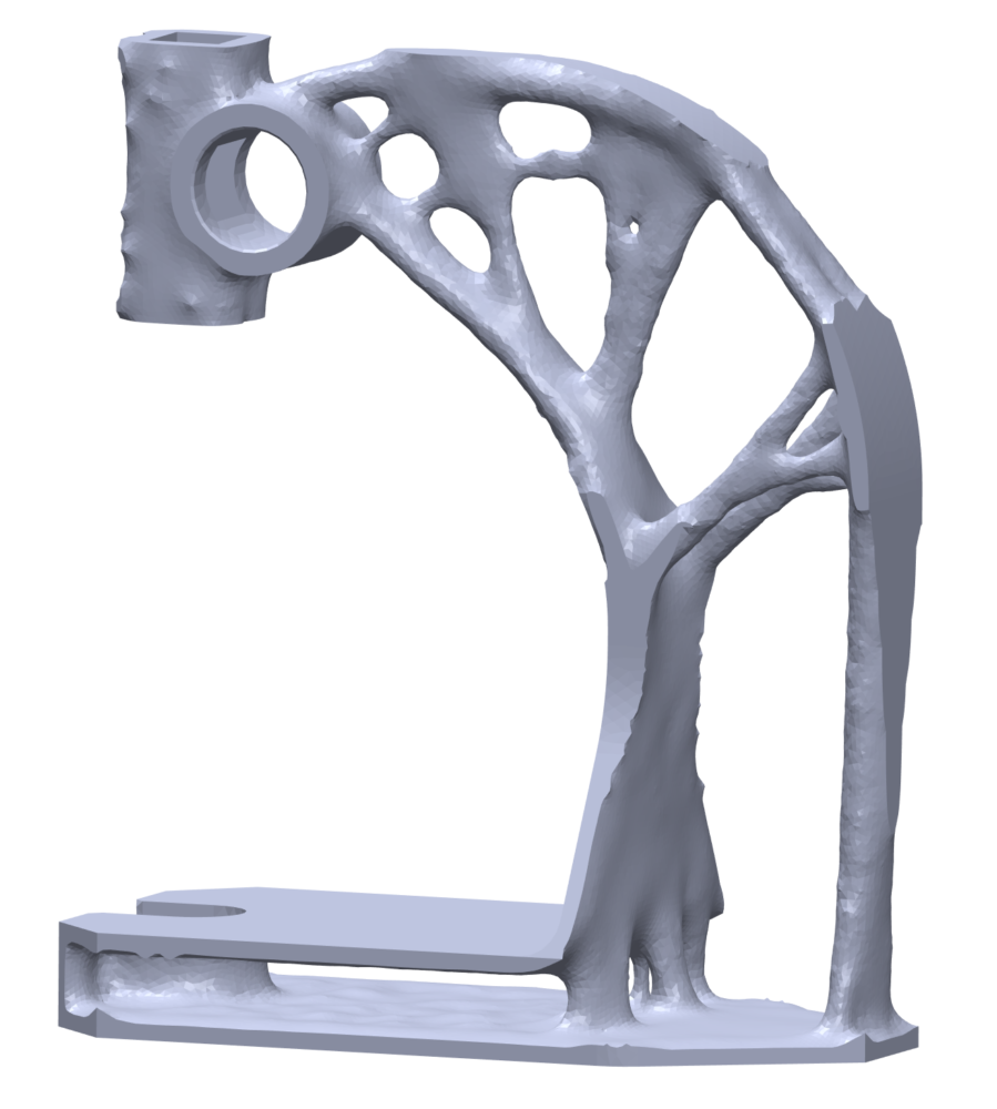
4- The next step was to run the study itself. After trial and error and seeing that this was a really demanding computation for the computer, I found an equilibrium between the computation time and the definition of the mesh element size (the smaller the better). The final product came after a computation time of 2 hours and reduced by 75% the weight of the body of the press. Here is the result:
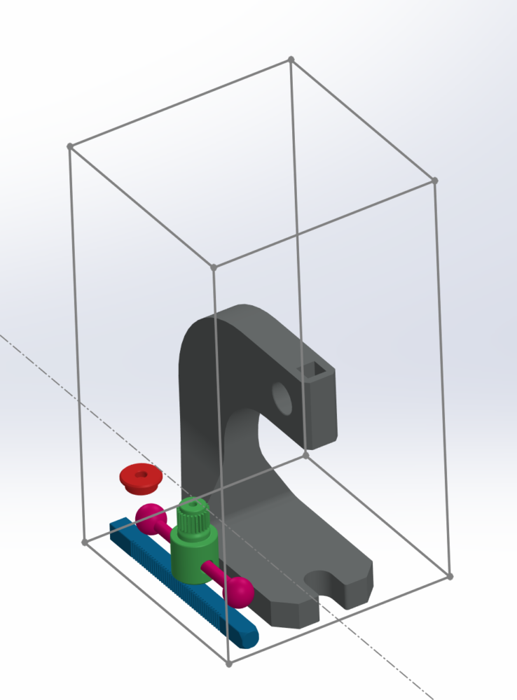
5- One I was satisfied with the result of the Topology study and I had all the other components designed. I checked in the 3D printer manufacturer (Formlabs Fuse 1) the achievable tolerances of the printer and how to orient the parts inside the bed to achieve the best finish. By the way, this printer is a new SLS printer in the Idea Forge. So, here is how I arranged the diferent parts in the bed. Once I had the assembly file on solidworks I exported it as one STL file (this is an option when exporting any STL file).
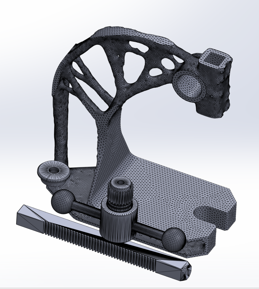
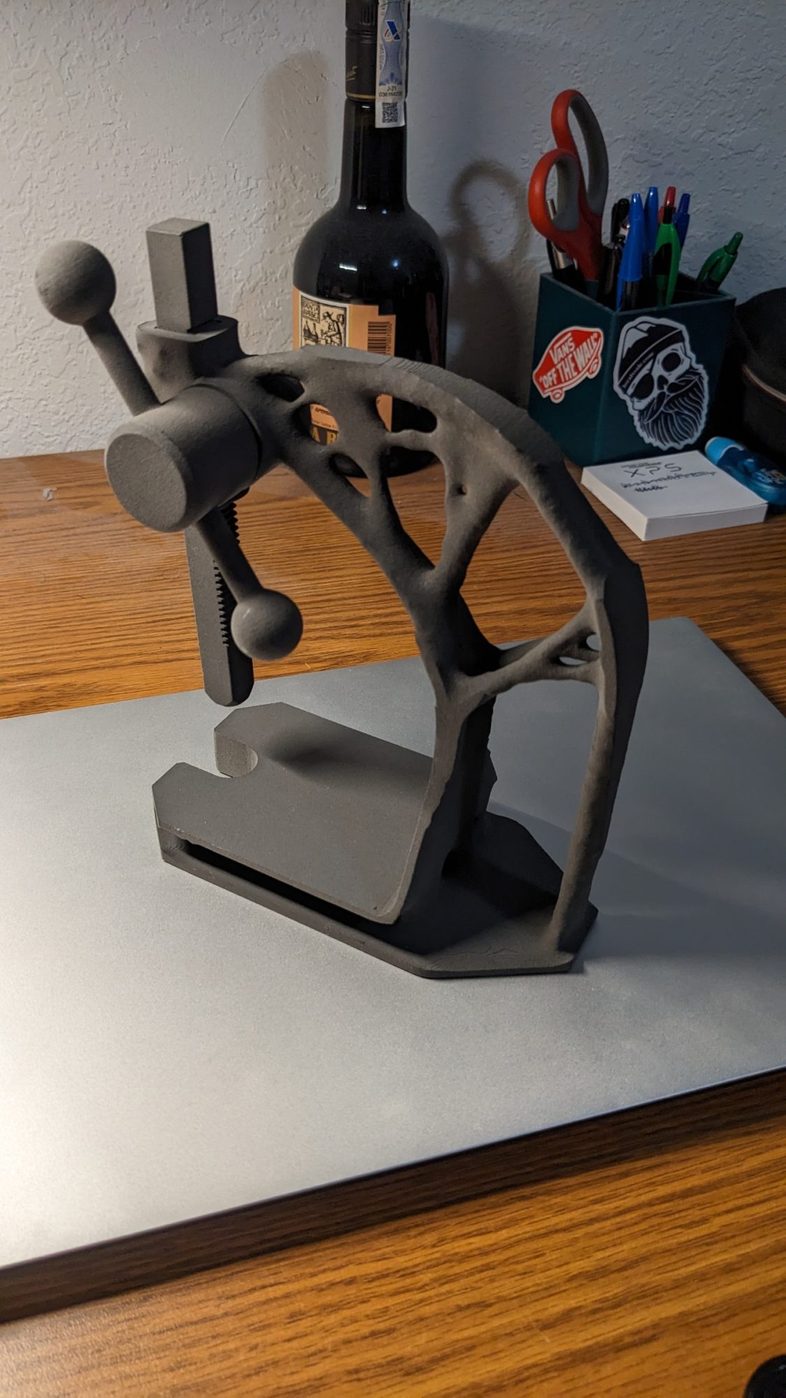
6- Once I had the STL and consulting some doubts and details with Patrick of Idea Forge, I sent the request to print the STL file. After paying and waiting 2 days, here is the result:

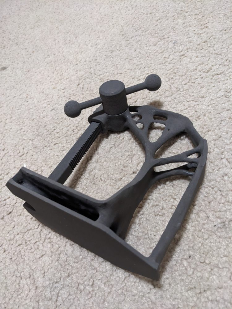
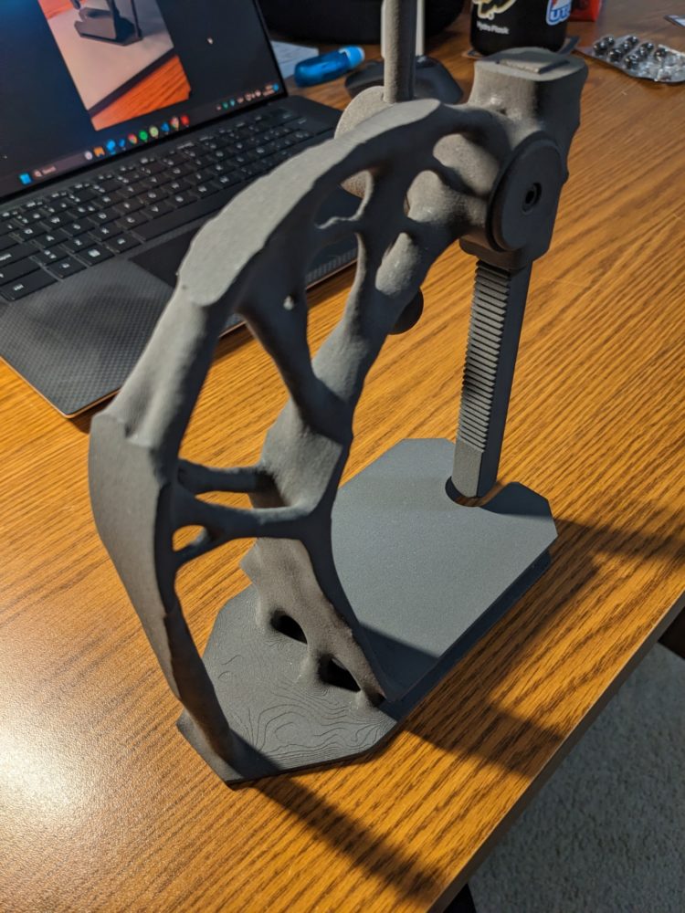
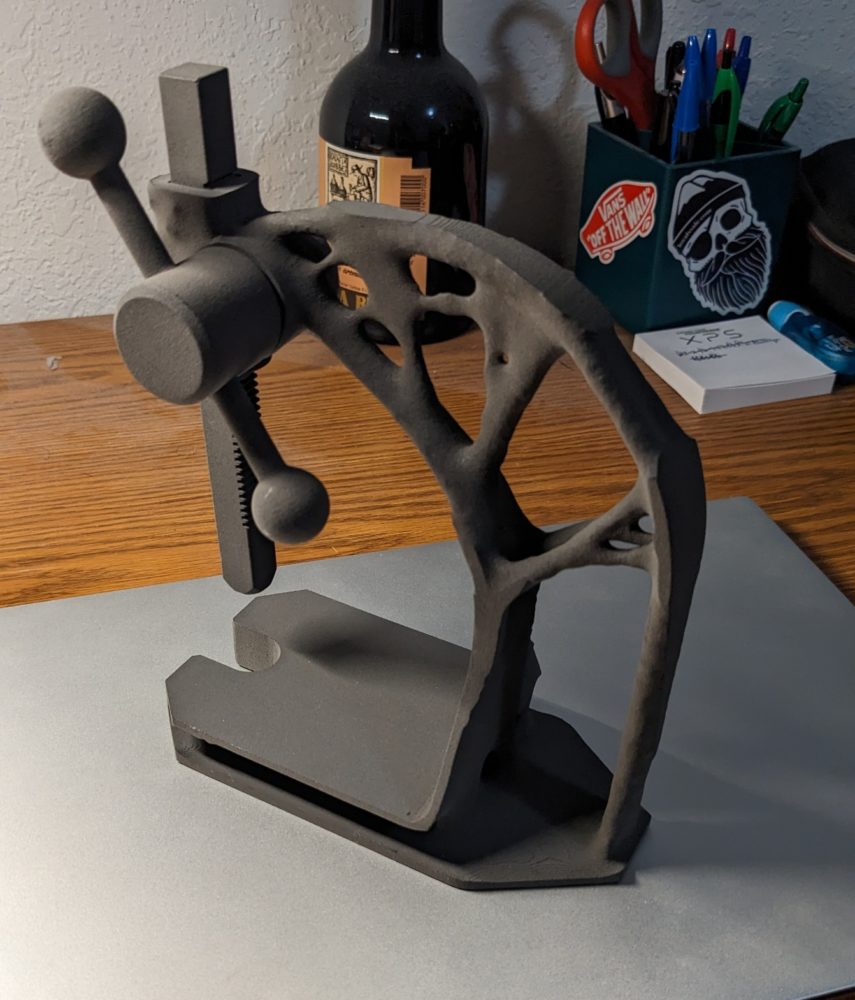
As a conclusion I would like to say I am very pleased with how it turned out. It satisfied all my goals and don’t differ much from what I was imagining when I chose this project. I have to say I haven’t had any major complications (the only one might be the inmense time required to run this studies with the computer). It also has served me not only as a way to create an appealing object (at least for me), it also helped me improve and expand my knowledge in CAD design and Solidworks software, discovering a whole new concept and module I didn’t know before. Those tools, that won’t stop being improved, open a whole new world of possibilities and ways to use this knowlede in infinite ways such as consulting or directly manufacturing it (as in my case).

1 Comment. Leave new
Very cool! I like that you used the topology study, this is a great chance to give this sort of technology a try as I’m sure it’ll be used a lot going forward. Did you just design all the parts so they could be easily assembled? Is there a bearing in there? What would you define the aesthetic to be on this piece? Nice work!