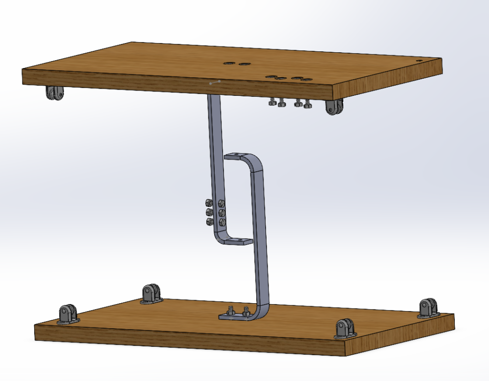
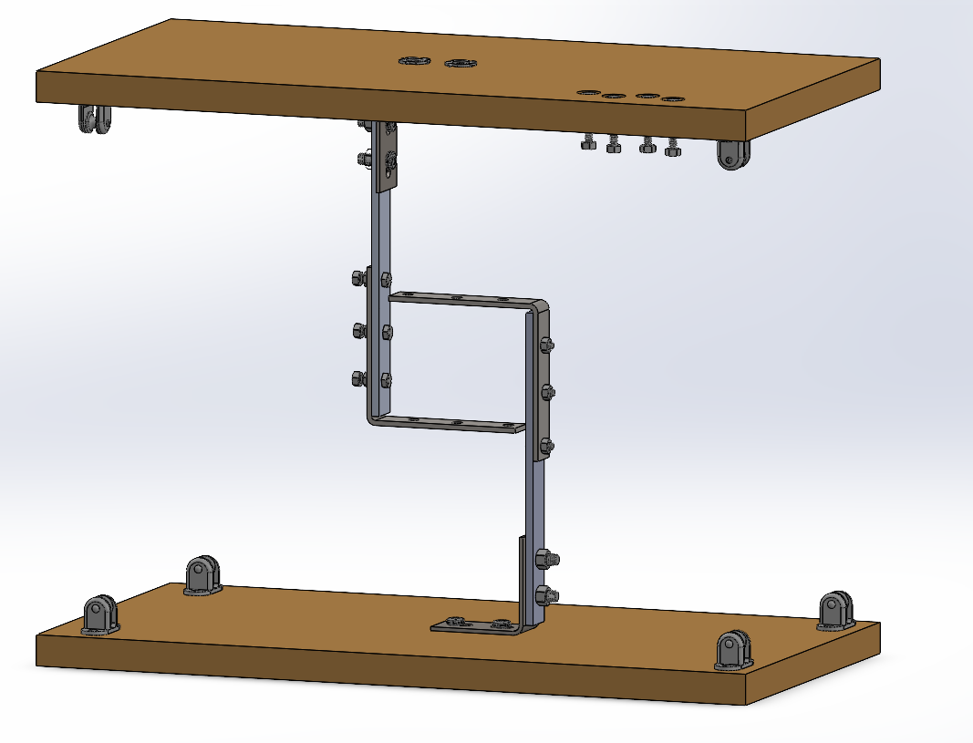
For my tensegrity table I have created two alternate designs based on both feasibility as well as to incorporate the “Industrial” and metallic design that I want to utilize within this project. Below you can see the two CAD files I generated for this table. Although the wire isn’t included you can see two general layouts for how this table would work, one including a bent quarter-inch aluminum bar and the other a flat bar with steel L brackets as well as several additional nuts and bolts throughout it. I think the one on the left may look cleaner overall but it would also likely be a lot less strong than the one on the right. The top surface of the table will have to be an inch thick which will be decently heavy and all rests on those center bars. For feasibility and reducing the amount of bending in the center bars I think the table on the right will work much better. However, in the future I do plan on iterating this desgin to change the middle – perhaps a welded steel bar to create the flat portions at the top and bottom. The only reason I didn’t include that here is I have no welding experience currently and also drilling holes in steel is much more difficult than aluminum.


