Organic Desk Fountain Design Preview
I want to make a Water Fountain that can sit on my desk. These systems are often battery or USB powered with a small pump to bring the water upward. I have seen these in offices acting as a calming visual and auditory element. An example of a Desktop Water Fountain is shown below:

Figure. 1 Desktop Water Fountain
The flowing water in these fountains will act as the dynamic aspect of my project. Although I would still like there to be more movement which I will further discuss later. Another aspect of this that will work to my advantage its that water easily plays into the Organics Aesthetic.
Organic pieces of art are inspired by nature and have many often time chaotic curves that when viewed as a whole offer a sense of harmony. The nature inspiration for my final project is standing at the base of a tree and looking upward. While everyone can do this themselves, I have attached an image below:

Figure. 2 Upward View of a Tree
I also wanted to show another example of art inspired by organics and nature. Nature almost always follows the path of least resistance. This is what determines which direction tree limbs grow and even how pain spreads on canvas. With this commonality one can often look like another as shown in the art by Sana Shaw below:

Figure. 3 Sana Shaw “The Essence of Plants”
The initial reason I decided to move forward with the Organic Aesthetic was because of the Topology Optimization tool in SOLIDWORKS. This process maximizes the stiffness to weight ratio of a given component. Basically, Topology Optimization strategically takes away material from the part while attempting to maintain maximum resistance to a load.
The outcome of these simulations are very organic looking parts that are striking for viewers. To test this tool, I thought to benchmark it against a common loading case such as a cantilever beam as shown in the figure below:

Figure. 4 Cantilever Beam Load Case
Along with the common knowledge that the strongest shape is a triangle, the outcome of these simulation often show triangles. The image below shows the outcome of a Topology Optimization simulation of a cantilever beam:

Figure. 5 3-D Printed Cantilever Beam Topology Optimization Output
I ended up 3-D printing the outcome of the simulation as shown above because I really like the shapes and now use it as a bookmark. While the image above shows a 2-D load case, the same process can be done with 3-D models. Following the idea of triangles, I made a Triangular Prism in SOLIDWORKS and added various loads to it. The 3-D printed outcome is shown below:

Figure. 6 3-D Printed Triangular Prism Topology Optimization Output
Simulations using Topology Optimization at its highest setting take multiple hours which ended up making this process take multiple days of work. I found it worth it sense this is the main component of my project.
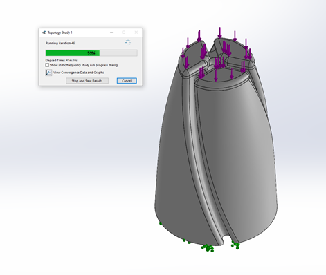
Figure. 7 Simulation Progress
The model in the image above is basis for what the Topology Optimization tool takes away from. There is a channel throughout the middle of the component for water to be pumped up though and then grooves down the side of the part for water to flow down.
While it is often difficult to get a visually appealing output of a Topology Optimization Simulation. Balancing manufacturability and holding true to my inspirations was tricky. I managed to get it right after ten tries. The figures below show off the crazy organic structure:

Figure. 8 Topology Output Side View
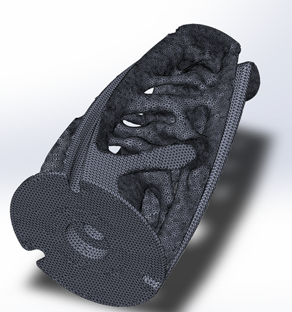
Figure. 9 Topology Output Bottom Isometric View
In these figures, each small triangle is an element in the Finite Element Analysis used in Topology Optimization. The only way to really manufacture components like this is 3D Printing with a lot of infill. Even then, the surface finish is lackluster. For this issue, I bought some PLA sealant, which causes an exothermic reaction and should smooth out the final 3D Print of the Topology Optimized structure and provide a nice shine.
I am using a bearing at the bottom of this piece where hopefully in the absence of friction and the water flowing at an angle down the side will cause the whole thing to spin. The figure below shows a cross section of my design for the fountain:
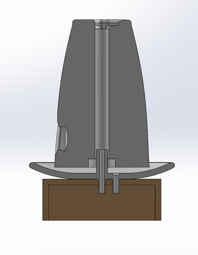
Figure. 10 Fountain Cross Section
Below the top component of the fountain, a dish is present to capture the water as it falls. It also acts as the interface for the tubing of the pump. This dish sits on top of a simple wood box to emphasize the tree inspiration.
With all of the design work completed for my final project, I have start to gather components and begin fabrication. The image below shows the required hardware for my Desktop Water Fountain:
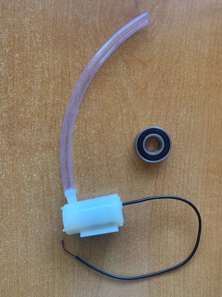
Figure. 11 Fountain Hardware
The pump is rated for 3-6 V which determines the pressure head. I plan on implementing a potentiometer to be able to dial in how high the water goes. The bearing is sealed and should allow water to get through it. However, this makes the bearing slightly harder to spin. Hopefully, this doesn’t stop the Fountain Head from spinning due to the water’s flow.
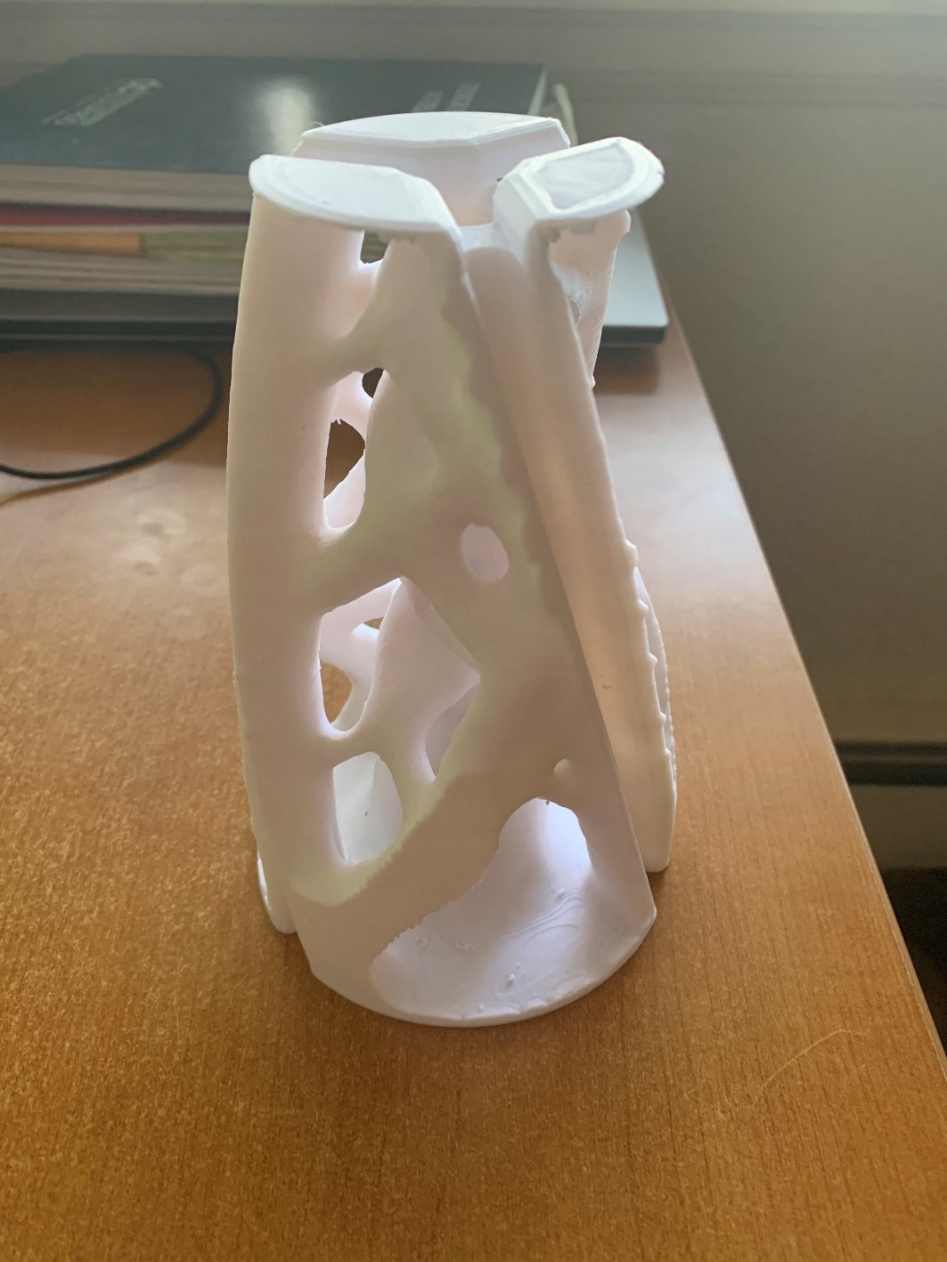
I have also been able to 3D print the fountain head. However, I have not added the sealant, so it still looks a bit rough. An image of it is shown below:
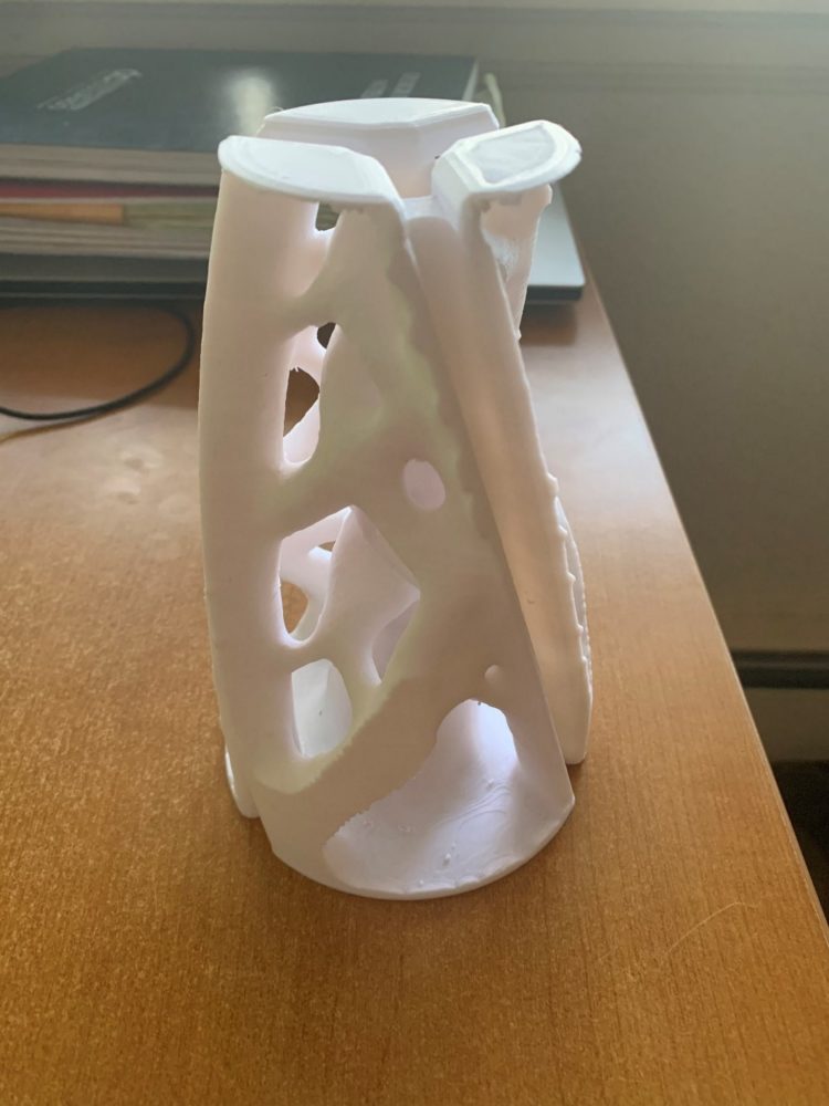
Figure. 12 3D Printed Topology Fountain Head
Picture 3: https://i.pinimg.com/originals/cf/ef/fd/cfeffd2d1fe846e5e499a48671a2d6ac.jpg
Picture 4: https://mechanicalc.com/static/img/FEA/Validation/Cantilever/cantilever-beam-01.png
Picture 5: Original Content
Picture 6: Original Content
Picture 7: Original Content
Picture 8: Original Content
Picture 9: Original Content
Picture 10: Original Content
Presentation Video Link:

6 Comments. Leave new
Nice Article….
https://marinerspoint.in/centrifugal-pump-parts-working-diagram/
Good article
https://mechanicalboost.com/centrifugal-pump-an-overview/
Great work so far Michael,
I really like how your fountain is coming out, and what an awesome way to get some more experience with the Topology Study Feature of Solidworks. I’m looking forward to seeing how everything looks once you apply the sealant. Do you plan to paint the fountain any other color that might take on the organic aesthetic a little better than white? I don’t know if it is possible, but if the sealant gives the print nice enough of a finish you might be able to apply some sort of paint on glaze so that your fountain looks something like the image you shared in figure 3! Take or leave that comment, it may not even be possible, all in all great work!
Thanks Jake for the comment. The sealant does give a nice surface finish for paint to adhere to and this came in up in the critique from my pod group. I haven’t yet decided if I want to paint the fountain head but I know it is a good option moving forward.
Hi Michael,
I really like the topology optimization tool’s results and how the organic shape looks on your water fountainhead, it gives it a very appealing style and I can see it also makes it lightweight and easy to move around. How did you select your pump? Is it a standard for fountains like these? Did you perform a fluidic calculation to see how much pressure it is required to pump the water to that height? What will the volumetric flow be?
Hi Gary, great question. I selected the pump based on the range of the pressure head. Basically how high up the pump can push the water. I designed the rest of the system around this value and am implementing a potentiometer to be able to dial in how high the water goes. I didn’t spend too much time thinking about volumetric flow rate but in preliminary tests with the pump it seems to be a good amount.