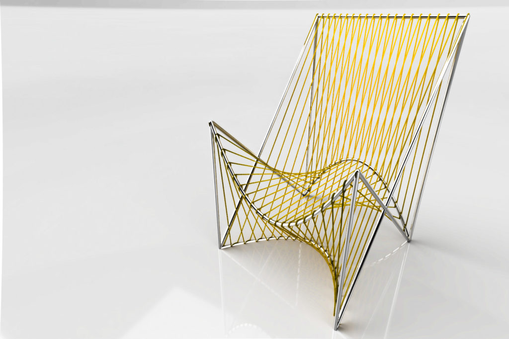
I’ve been working on the design of my climbing rope chair, and I’m getting more and more excited about the idea. I made a more complex grasshopper definition to create a whole chair with a metal frame modeled in it. I still wanted to mess with the shape, but I needed to include the supports that would hold the curves in place, and the curves needed to have thickness with the ropes wrapping around them. This grasshopper definition makes pipes out of the boundary curves, then makes pipes between the ends of the curves. It also makes thinner pipes out of all the rope segments, and pipes that circle the end curves to look like rope wrapping around them. It also models the rope wrapping in an hourglass shape around all four curves. There’s probably a much more concise way to do this, but I’m new at grasshopper so I used a new component for each piece of the frame.

I can control the radii of the frame pipes and the rope separately, as well as the number of times the rope winds around.

The rope is only for the renderings and to get a feel for what the chair will look like. It doesn’t have to be modeled precisely. But the frame is what I need to make to create the chair. I originally decided that I wanted to use somewhat thin metal tubes to create this frame so that I could have as little as possible to interfere with the cool visual effect of the rope inverting curvature. I plan to use the 5 axis CNC machine to create the joints that will connect the vertices of the frame, and I’ll use a pipe bender to bend the curved sections.

I made a lot of iterations to the design in this stage, But here’s the one I like the best. All three curves are bent to the same shape, which will make them easier to manufacture. Also I think the symmetry looks nice. I decided to make the top tube straight so that the straight lines of the back contrast with the curves of the seat. I also made renderings in order to visualize the final project


I really like the way this chair looks, But I ultimately decided that welding or CNC machining joints for each of the corners isn’t feasible to finish in time for the end of the semester., So, I’ve come up with a new design for the frame. I’ll make the outsides out of wood and drill holes that the pipes will fit into. This will allow me to use much simpler fabrication techniques, and still end up with a high quality product. Here is my new design using this method:

I’ll be able to cut these pieces of wood to the correct size and carve out the notch where they cross in the ITLL machine shop, also I’ll be able to use the pipe bender in the ITLL to bend these tubes to the correct shape. I’m purchasing materials this week and plan to start construction early next week.


1 Comment. Leave new
[…] New Designs and Construction Timeline […]