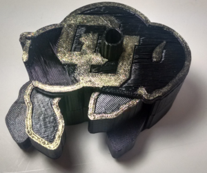
Run Ralphie Run – What is it?
Run Ralphie Run, otherwise known as the ‘Mechanical Buffalo,’ is an automata toy made from the Colorado Buffaloes logo. This automata is actuated with a small peg that rotates 30 degrees and causes the legs to move. Then, the peg is rotated 30 degrees in the opposite direction to restore the legs to their original orientation. Overall, the toy consists of 9 components, 2 static and 7 dynamic. All 9 parts are printable on a standard FDM 3D-printer and can be assembled as a DIY kit.
Here is an animation of the toy in action!
Aesthetic Considerations
The aesthetic considerations of this toy were three-fold: 1) capture the essence of Japanese ‘Karakuri,’ 2) create an attractive yet easy-to-assemble DIY-kit, and 3) CU Buffs theme.
Karakuri
In the 1600s, Karakuri, or mechanical trick, became a part of Japanese culture. They were essentially puppets that mimicked the motion of living things without showing the onlooker how it was done. Much of this automation was done using cams, springs, linkages and other mechanisms, which were all hidden from view inside a box. Though many other ancient cultures also created automatons, Karakuri puppets are noted for their particular attention to subtle details. Their influence is still seen today in modern robots. Here is an awesome example of Karakuri.
In order to pay homage to Karakuri, this toy is designed with all of the gears housed internally and hidden from view. The user only sees the peg that sticks out of the top and the “body” of the buffalo. Once the top half of the outer housing is snapped into place, it cannot be removed without breaking the toy – so the gear transmission cannot be seen with a functional toy. Additionally, the legs move with a gait pattern that attempts to mimic the motion of a four-legged, hooved animal.
State 1: Front Left – Forward, Front Right – Back, Back Left – Back, Back Right – Forward
State 2: Front Left – Back, Front Right – Forward, Back Left – Forward, Back Right – Back
DIY Kit
The important considerations for the ‘do-it-yourself’ aesthetic were ‘coolness’, accessibility/flexibility, and ease of assembly. The coolness factor was addressed through the use of unique/unusual looking internal designs and sleek external housing components. Most of the parts have relatively complex geometries, making the kit an exciting application for household 3D-printers. Since the kit is 100% 3D-printed, a simple upload to Thingiverse should allow many 3D-printer enthusiasts to print the buffalo on their chosen 3D-printer right away. Assembly is straightforward because all 9 components are unique and there are locating features on each gear to point out their intended initial orientation.
CU Buffs
In order to keep the CU Buffs theme, the entire assembly is cut from a shelled extrusion of the Ralphie logo. The most difficult aspect of maintaining this aesthetic was creating the legs. Rather than using legs of arbitrary shape, the existing legs on the logo were cutoff and made into separate parts. Then, these parts were modified significantly to allow them to rotate properly within the toy about a fixed pivot. In order to make this work, several geometric relations were used, which will be discussed in the next section.
Engineering
Component Overview
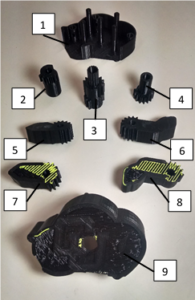
1 – Ralphie B (Chassis)
2 – Left Gear
3 – Center Gear
4 – Right Gear
5 – Back Left Leg
6 – Front Left Leg
7 – Back Right Light
8 – Front Right Leg
9 – Ralphie A (Cover)
Design Specifications
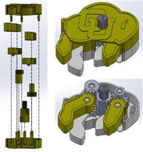
The overall size of the toy is approximately 3.75in x 2.5in. This allows each component to fit onto most 3D-printer beds, including the Lulzbot Mini. It weighs about half a pound when made out of ABS, though this could be decreased depending on printer infill settings.
The design was iterated from a buffalo box, to a buffalo with moving legs, to a buffalo with mechanized legs. The last of these iterations required several redesigns. The box halves are held together with an interference/snap fit feature.

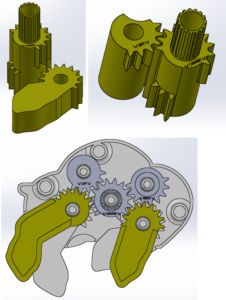
Gears are used to transmit motion from the center peg to the legs. The back left and front right legs are directly driven to the center gear while the back right and front left legs use an intermediate gear to reverse their direction relative to the other two legs. This configuration creates the intended gait of the buffalo. All gear ratios are 1:1.
Gear Design
In order to create the gears, approximate gear locations were roughed into the Solidworks assembly, then a sketch was created with circles at each projected gear location. Then, these circles were made equal and tangent. The diameter of each of these circles became the pitch diameter of the gears (the point at which gears mesh).

Once this pitch diameter was determined, standard gear equations were used to find gear tooth parameters. The most important for design were addendum, dedendum, and tooth thickness. 15 gear teeth were chosen to make the gears printable at various tolerances and still provide enough precision to comfortably drive the legs. The following MATLAB script was used to solve for these parameters.
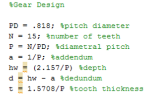

These gear teeth were applied to each component and Solidworks’ gear mate capabilities were used to dynamically analyze the performance of each gear. In various places, it was very obvious that the gear teeth would interfere with the walls of the box, so an interference analysis was performed to determine required modifications. This resulted in the removal of several teeth from every gear. Also, lengths of gear teeth were removed to prevent gear teeth from meshing with components they were not supposed to mesh with. For example, the center gear does not directly drive the front left gear, so the teeth along that interface were cut short.
Manufacturing
Complete kits were made using two different machines: a MakerBot Replicator 2x in the IdeaForge and a personally owned Rostock Max V2. Standard ABS filament was used on the MakerBot and standard PLA filament was used on the Rostock. With a design allowance of 0.050in, all of the components fit without much post-processing or filing using both printers and materials. The tradeoff with this allowance is that the gears occasionally did not mesh perfectly, making the motion of the legs a bit rough. However, every version that was printed still performs capably at all orientations – the toy can be held upside down and continue normal function.
Layer height and infill percentages did not appear to affect performance. 0.4mm layers (low precision) and 20% infill (low infill) were both used successfully. Some support material was used on the center and left gears, but this was easily removed with pliers and did not affect performance either. If the parts were manufactured using SLA or another high resolution 3D-printing method, the allowances could be tightened more for high performance.
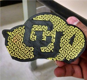
Finally, in order to further conform to the CU Buffs aesthetic, gold nail-polish was used to accent the final toy. This was an optional step.
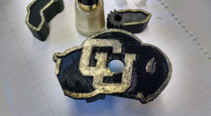
A second extruder could also be used to create this same effect, though not all printers have this capability.
Costs
All costs were overhead. All manufacturing was done for free using filament that was already owned, and the nail polish was borrowed. This is how the project was intended – a DIY, 3D-printed kit.
Final Thoughts from Sreyas
This has been a very rewarding and interesting project to work on and I definitely plan on continuing it further in some form. I will discuss these plans in next week’s report. More than anything, I am ecstatic that I was able to create a mechanism that uses 3D-printed gears. I never previously had the confidence to do so. I look forward to creating more geared devices in the near future!


6 Comments. Leave new
Your project turned out really well! Have you considered making an iteration where the user winds up a torsion spring and the buffalo runs on it’s own? Kind of like the wind up toys that you would find at Into the Wind. I’ll keep an eye out for it on thingiverse!
I like your aesthetic of Japanese puppets and incorporating the CU Buffs logo. I think it is a very successful project and would be a great new asset to the CU Bookstore to sell. I also liked your idea of making it easy for other people to access and 3D print themselves and put together. I thing this is a great project that fulfilled what you were trying to accomplish. Wonderful work!
Sitting next to you in expo really gave me the opportunity to really admire your project. I never realized how difficult creating gears could be. The best part of your project in my opinion was the aesthetic you were able to produce. You were really able to demonstrate the toy kit aspect that I think you were going for. It looks really professional. Were you still planning on implementing the use of a motor to make it independently walk across a table on its own? I think that would be an incredible improvement!
Thanks dude! Trust me when I say that I was surprised by the challenges this project threw at me as well. However, I am very happy with the result. I’m really looking forward to uploading this to Thingiverse!
I could certainly try to implement a motor now, but I would love to make several redesigns before that in order to make it actually walk rather than just letting the legs move. As it is, the center of mass is a bit too part up front and there is not nearly enough space inside the box for even a small motor. Also, continuous rotation in this configuration would also require some re-work – and linkages would be tough with the limited space inside the box. However, if wind-up toys can do it, I’m certain it is possible. I’d love to disassemble one at some point and see what’s going on in there. That would be pretty epic!
This report really shows your design process perfectly and helps people who potentially want to do the same! Great work on this write up! I also love how you talked about karakuri and how you wanted to stay true to that style. You definitely accomplished that and I love how you were even able to make it so it won’t open unless you break it! Amazing work! What do you plan on doing with this? Also do you want to keep making things like this but with different logos or themes like maybe a toy car next?
Thanks Rachel! The next immediate step for me is to make a stand for it so it can sit on my mantle, but now that I know how to make 3D-printed gears, I feel like the sky is the limit. A toy car would be amazing! I also thought about making a model of a real bison and make the head and tail move too (using different gear ratios). Either way, I’m excited to see what personal projects lie ahead!