Project Description
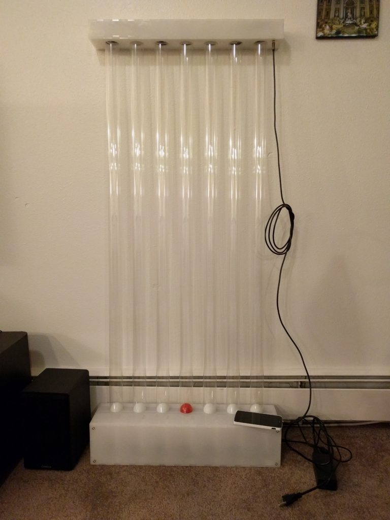
The Levitation Audio Visualizer is a dynamic sculptural-like device that allows a user to interact with music in a new way. Seven ping pong balls are suspended in clear columns using fans, and their suspended height is changed according to filtered frequency bands of input audio. The enclosure is made of opaque white acrylic which is illuminated by high power RGB LEDs.
Project Goal
The foremost personal goal that I had for this project was to create a unique and interesting piece of art that intrigued on lookers. I also wanted to use this project as a learning experience to explore different aspects of electronics and programming.
Project Inspiration
My initial inspiration for this project came from the original implementation of frequency spectrum audio visualizers. These visualizers break the audio spectrum in to discrete chunks, and adjust bar levels which correspond to the amplitude of each range. They usually also include bright colors that correspond to bar height, or to distinguish the each range. As I started thinking about it, I realized that we have some innate fascination with objects that appear to defy gravity. If you have ever seen the rock sculptures that people build next to Boulder Creek in the summer, you will understand the intrigue of balance/levitation that I am attempting to describe. I wanted to try and capture this quality, and incorporate the the aesthetic in my project.
Target Aesthetic
Primarily I see the levitation audio visualizer as a combination of minimalism and information visualization. The product itself is almost entirely devoid of color, as the enclosure is entirely opaque white, and is simple geometric shapes. It also contains some elements of generative art, in the way that the dynamic ball movement is an automated response to music. As the artist, I do not actually control the visuals that the user experiences.
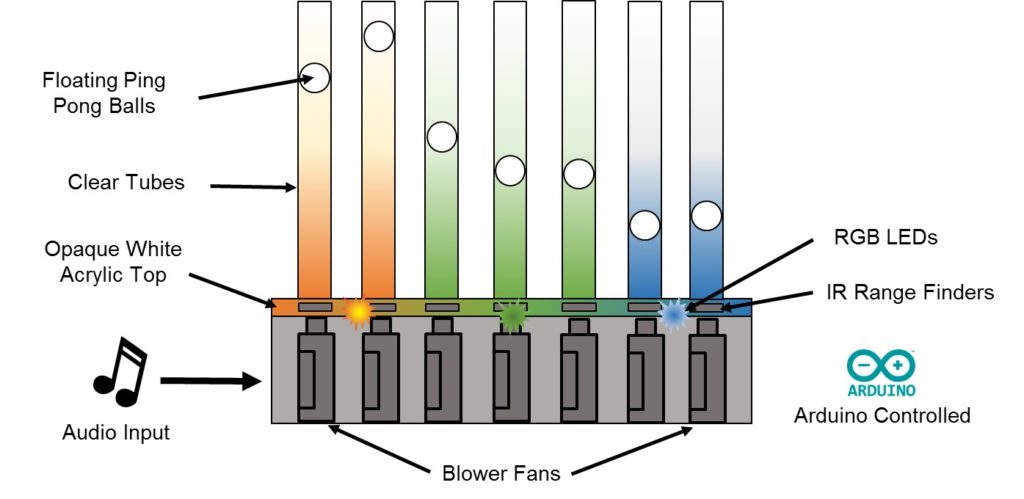
Design Review Concept Image
Enclosure
The enclosure for this project consists of 7 clear tubes, a bottom box, and a top box. The bottom box houses each of the 7 fans, which are connected to the clear tube using a pipe clamp. To access the fans, both the front and back panel are removable. This makes fan installation and wiring significantly easier. The bottom box also contains the fan driver board, input power cord, and on/off switch.
The top box contains the ultra sonic range finders, high power LEDs, micro controller, and audio filtering electronic boards. The range finders need to sit precisely axial to the tube so that the signal does not bounce off the internal walls. To do this, I laser cut a piece of acrylic that the sensors press into. A small screw keeps the sensors from falling off. A pipe clamp is then used to secure the acrylic piece to the top of the tube. To connect the signals and power between the top and bottom box, RJ45 Ethernet cable is run on the side.
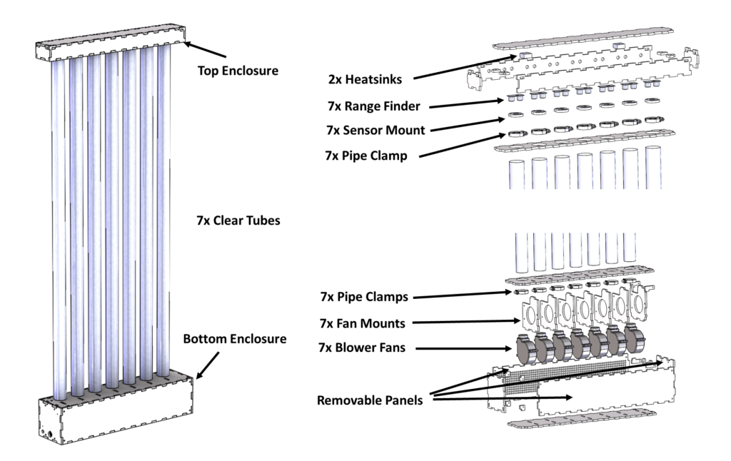
CAD Images of Final Design
All of the design was done using SolidWorks. These files were converted into DXF files, and laser cut in the ITLL from .250″ thick opaque white acrylic. Acrylic cement was used to weld the acrylic pieces together, and 2 part expoy was used to glue in all of the plastic connectors. The removable panels are each held in place by 4 #8-32 screw, which fasten into little acrylic blocks that were tapped in the ITLL machine shop. The circuit boards are each held in place with 4 #2-56 screws, and also fasten to the panel with tapped holes.
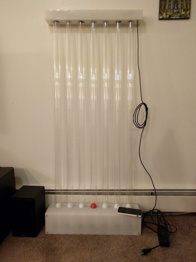
Assembled Audio Levitation Visualizer
Electronics
Micro controller: For this project I used the Teensy 3.2 development board. The primary reason for selecting this board is that is has 34 GPIO, which is a huge amount of available pins. It also has 12 dedicated PWM pins, which were needed to control the RGB LED channels and fans. At only 1.4″ x .7″, it’s Cortex M4 processor makes it far more capable than an Arduino, while still only costing $20. It can be programmed in the Arduino environment using the Teensyduino add-on, and can utilize most libraries developed for the Arduino.
Fans: To levitate the ping pong balls, each column required a fan to provide lift. I selected centrifugal blower fans as they are better suited for providing high pressure compared to the more common axial (computer) fan.
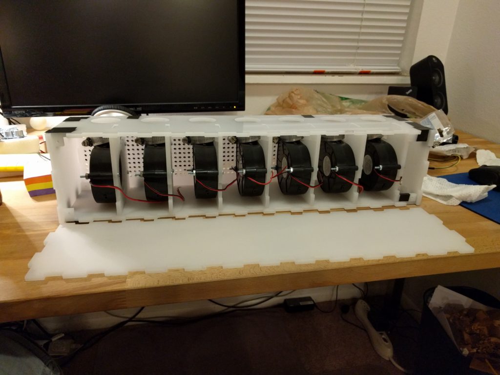
Seven Blower Fans Mounted in the Enclosure
Although the fans only require 12V DC to power on, I wanted to be able to control each fan, and set the speed at which it is spinning. To do this, I wired each fan up to an N channel logic level MOSFET. To control how much air each individual fan is blowing, the micro controller sends a varying PWM signal to the MOSFET gate channel. To deal with the large back EMF and generated voltage spikes, each fan has a Schottky diode across the inductive loads.
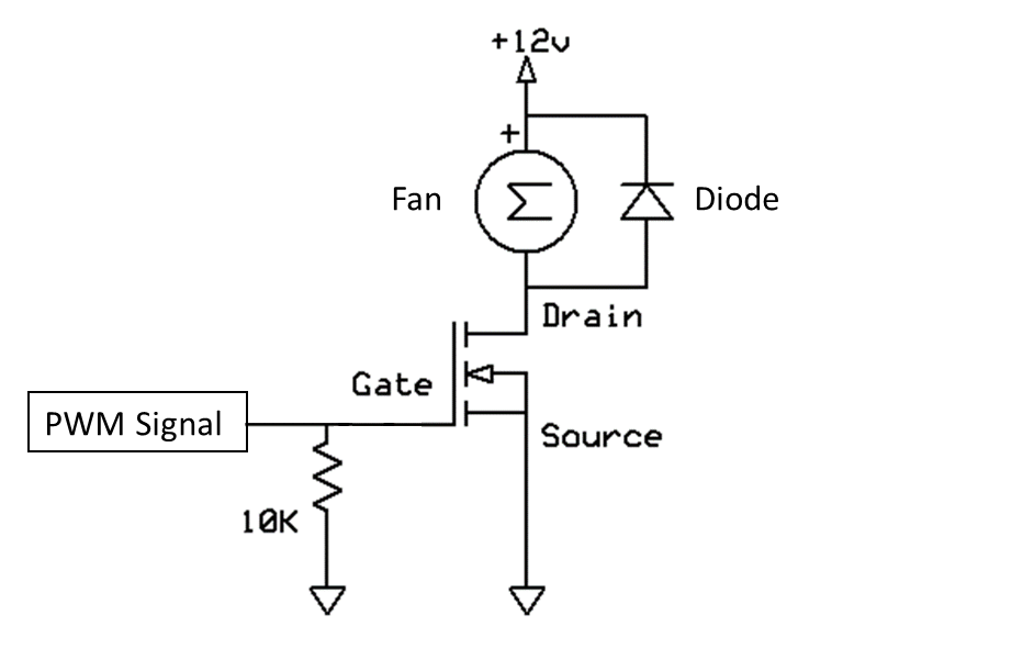
MOSFET Fan Driving Circuit for 1 Fan
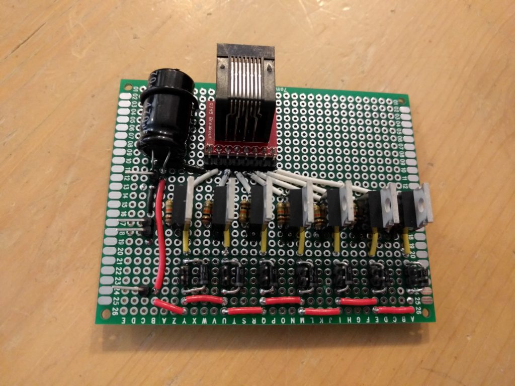
Assembled Fan Driver Board
Audio Filtering: To filter input audio, I used the MSGEQ7 IC. This chip allows you to input the audio signal, and it will assign a value between 0 and 1023 for each filter range: 63Hz, 160Hz, 400Hz, 1kHz, 2.5kHz, 6.25kHz and 16kHz. To test the accuracy, I used an online audio generator to play only frequency at a time. When the specific frequency falls into one of the ranges, that value increases, while the other values don’t.
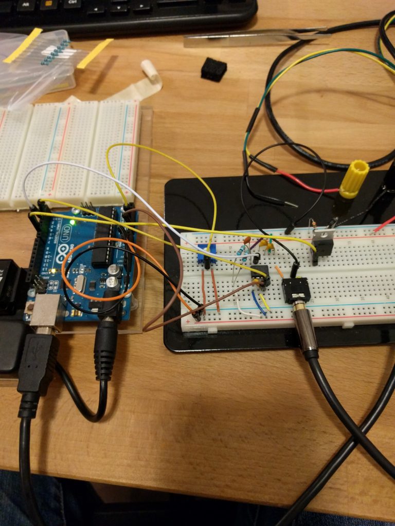
Bread Boarding the Audio Filtering Circuit
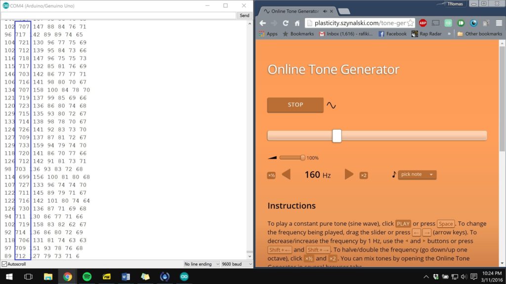
Arduino Serial Monitor Reading 160Hz From Tone Generator
RGB LEDs: To illuminate the top enclosure, 2 high power RGB LEDs were used. Since each color channel requires a different voltage (Red 2.6V, Blue 3.8V, Green 3.8V), and the input power is 12V, I needed to create an LED driver board. This board consists of one MOSFET for each channel, which controls how much of each red, blue, and green is added to the color. Since each color is pulling 700mA, each channel also received a dedicated voltage regulator. A buck converter was selected for this application, as a switching regulator is far more efficient than a linear voltage regulator. As a result, the regulator pulls less power and does not generate high amounts of heat.
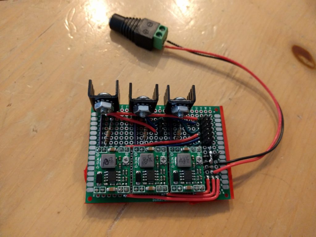
LED Driver Board
The LEDs still get incredibly hot, even after a very short duration of being on. To stop them from damaging them selves, I used the ITLL machine shop to machine little aluminum heatsinks to mount directly under the chip package.
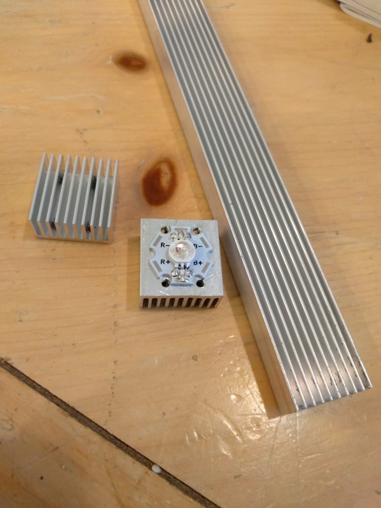
Machined Heatsinks for High Power LEDs from Barstock
Ultra Sonic Range Finders: To sense where the ping pong balls are located in the tube, each column has an ultra sonic range finder connected to the top of the tube. The sensors trigger a high frequency audio pulse, listen to the echo, and calculated the distance from the time between the return. Since I need 7 range finders total, which is a very large amount of pins, I used two analog 74HC4051 multiplexers. One multiplexer handles the triggering while the second handles the echos. This setup is actually fairly clever, as it allows you to effectively scan each sensors by continuously selecting the appropriate channel.
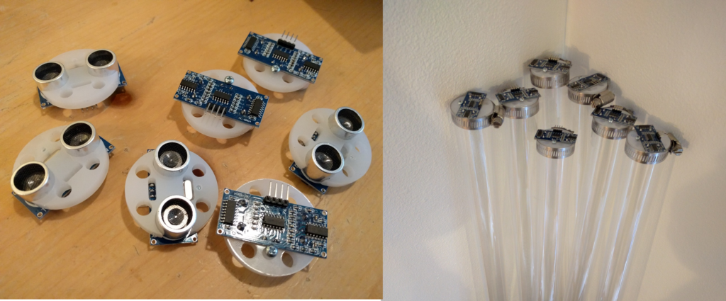
Range Finder Mounted Onto Tubes
Power Supply: The RGB LEDs pull a total of 2 amp, and each fan can pull up to 1 amp when on full power. If all fans were at full power, the project would pull 8A. I assumed that all of the fans would never be on full power, so I purchased a 6 amp supply. To power the unit, the user plugs the power supply directly into the side, much like a laptop charger. An embedded rocker switch allows the unit to be turned on and off.
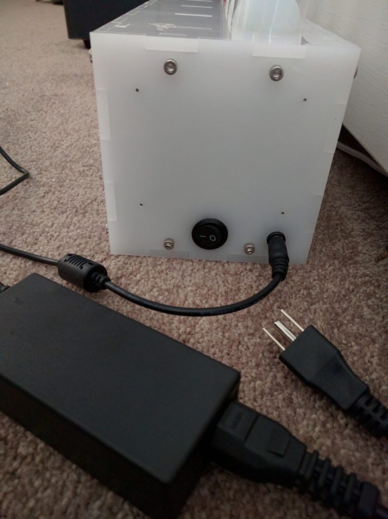
Power Supply and Off/On Switch

Electronics Mount to Top Enclosure Panel
Software
All the code written for this project was done in the Arduino IDE, using the Teensyduino add-on. The PID_v1 library was used for the control loops, and the NewPing library was used to interface with the HC-SR04 range finders.
The software routine for the levitation audio visualizer begins by reading successively the 7 outputs of the graphic equalizer display chip for each frequency band. These values correspond to the amplitude of the input audio within the frequency range. Next, it reads each of the 7 ultra sonic range finders to determine the height of the ball in the tube. To do this, channel 1 is selected on the multiplexers, and the NewPing library is used to turn the time delay between the trigger and echo into a distance. One it receives a value, the next channel is selected until all of the sensors have been read. Using the filtered audio values and the current ball location, the PID_v1 library is used to adjust the fans to move the ping pong ball to the correct location. The RGB LEDs are also updated to a new color to represent which channel has the highest amplitude. Below are the labeled pins that were needed on the microcontroller.
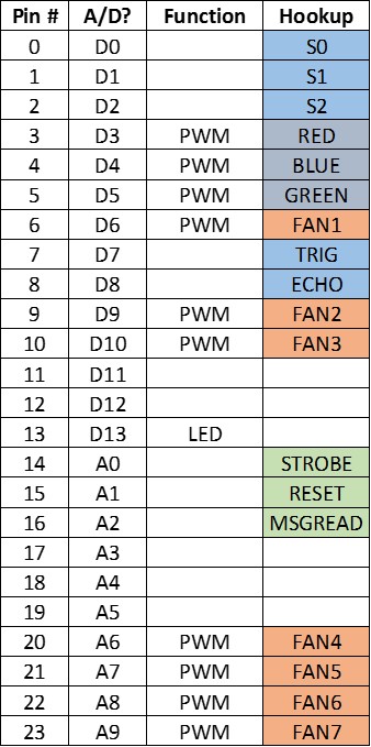
Teensy 3.2 Pin Out Table.
Major Obstacles
Levitation: During prototyping, I learned that it is not possible to “levitate” a ball inside of a tube by just turning on a fan. If the fan is too low, the ball will not raise. However, if the fan is tuned up, the ball will rise to the top. To overcome this, I realized I had to measure where the ball is located in the tube, and then continuously adjust the fan speed to suspend it. This required the implementation of a PID control loop to dynamically adjust the fan speed from a calculated height error. This is substantially more complicated, which increased my project scope significantly.
Measuring distance: To measure distance, I chose to use IR range finders. I quickly found out that IR sensors do not output a linear distance relationship. To compensate for this, I took some readings from the sensors at different distances which I measured with a ruler. Using a poly-line fit in MATLAB, I generated an equation to map the sensor output to distance. This worked surprisingly well. At this point, I found that the IR sensors are really only good at measuring up to 30in. I need to be able to reliably read at 50in, so IR was not going to be an option. The next thing I tried was ultrasonic range finders. After getting the ultra sonic range finders reading the distance to a wall accurately between 1 and 120 inches, I wanted to get it measuring in the tube. For convenience, I made a really long cable run so I could work with the piece on my desk while having the sensor on the top. After a few frustrating days, I finally figured out that the issues I was having with the sensor was due to the cable being too long. After resolving this, the sensors worked in the tube over the full range.
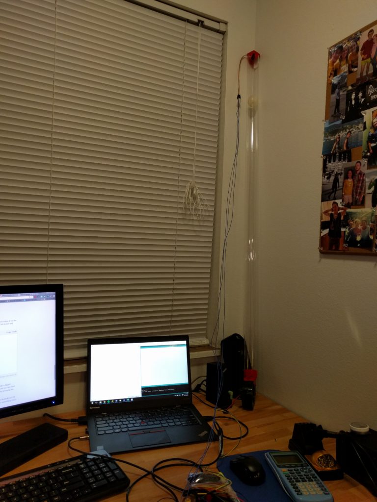
Prototyping Ping Pong Ball Levitation With Single Column
PID Control Loop: After a lot of reading online, and trial and error with a single fan/tube setup, I am still having substantial issues with finding the appropriate Kp, Ki, and Kd tuning constants. This obstacle has yet to be resolved, which prevents me from being able to use the audio to drive the heights (even though the audio filtering, distance measuring, and fan control are all working individually). My contingency plan for Expo is to “hard-code” some interesting patterns with the ping pong ball. This would fall short of my initial project goal, but would still be a really cool visual piece (and I could get the constants tuned when I have more time to explore during the Summer). I should have perhaps foreseen this difficulty during prototyping and changed to a more feasible project, but I am stubborn, like a good challenge, and really wanted to see some dancing ping pong balls.
Schedule
Below is a graphic version of my schedule, which details the sub tasks of each project stage. I closely followed the schdule through prototyping, but quickly fell behind after discovering that I would need to be able to close loop control the ping pong ball heights. The difficulties with the IR and ultra sonic range finders also burned a week during the middle of the schedule. I also encountered unforseen issues with the manufacturing process. I have used the laser cutter countless times in the past, and I have never had issues with the bed level and laser calibration. This was a large time suck, increased frusteration, and wasted half of a week. I drastically underestimated the time required to layout the electronics and solder the protoboards, which is a good lesson that I will keep in mind for future projects.
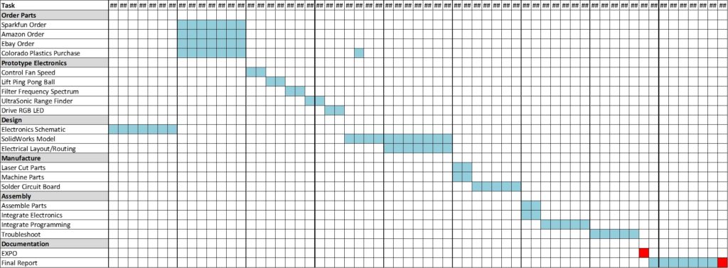
Schedule
BOM
I have compiled a bill of materials of all the components required for this project. The total cost was $203.40, which does not include components purchased for prototyping.
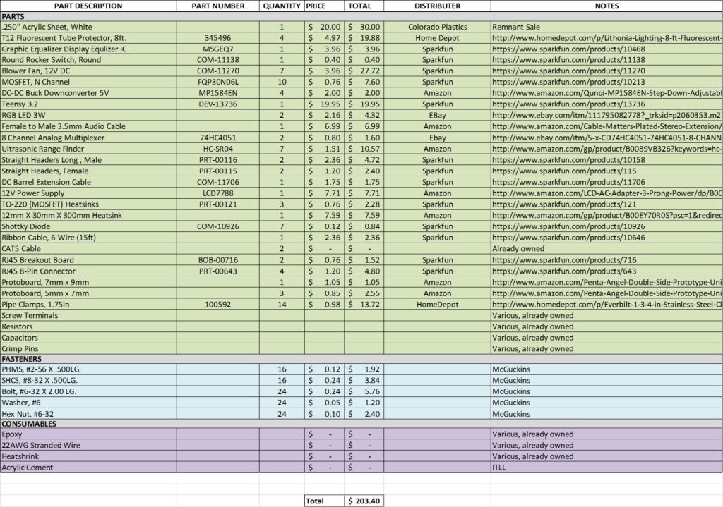
Bill of Materials

2 Comments. Leave new
I am really impressed with this project. I love the inspiration you used. I am impressed with how clean the final project looks. There is a great deal of electronics and fans that go into it and you did a great job of packaging all of the hardware. With projects I work on that is normally the hardest part for me, and you did an awesome job.
Thomas, I can’t say enough about your efforts and results on this project! You envisioned a compelling user experience, and put in a great amount of engineering to realize your vision. I am also impressed with your management of the entire project. The complexity of pulling all aspects (programing, machining, sourcing, and fabrication) presented a significant challenge which you handled like a pro. It was awesome to see the final product in action today at Expo.
You pointed out that there was some difficulties getting all the subsystems to work together in the final product. But those problems are surmountable with yet more engineering work. As for the aesthetics, I can offer a couple suggestions that may be interesting to explore. First, most of the product had the appearance of a custom built machine. The only give away was the ping pong balls that were off the shelf. So perhaps painting the balls or sourcing unmarked balls would be a nice refinement. I also think it would be interesting to use lotto balls with numbers printed on them; which would create an interesting commentary on the rise and fall of false hope that people experience. The only other suggestion that I may add would be to conceal the wire going from the bottom box to the top box inside a sheath to help lend to the mechanical mystery that makes this object so cool.
There was an issue with the fan outlet not being perpendicular with the flange. This causes the entire tower to be slightly out of plumb. To get ‘er back into plumb, just shim the back edge of the base.
Again, great work.