Introduction
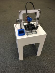
Additive manufacturing very well may be the future of making “things” and the advancement of 3D printers will revolutionize the way that everyday people get parts and products for use in their homes. The most common type of 3D printing on the consumer market currently is Fusion Deposition Modeling (FDM), which basically melts and extrudes a bead of plastic one row at a time, building up geometry with layer thicknesses of .05mm – .5mm. There are many models available for purchase, ranging from expensive machines (>$2500, like the higher end MakerBots or Lulzbots) to cheap kits and DIY setups (~$200+). Unfortunately, many of the more affordable options are a mess of wires, motors, and other components, and wouldn’t blend in to most people’s homes (unless they have a dedicated shop area). Since I don’t have a shop or workspace area, I set to design and build a 3D printer setup that would look just as good in my living room as any other appliance (TV, speakers, side tables, etc.).
Establishing a Design
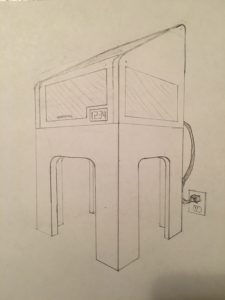
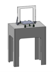
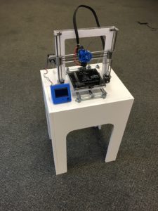
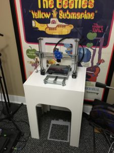
Right off of the bat, I knew I wanted to hide my harnessing, electronics, and filament better than this unit does, and put it in/on some sort of enclosure or stand. I didn’t have a free end table or workbench to put the printer on once complete, so I decided on building a dedicated stand, which is where I began to really think about aesthetics. Modern living rooms follow a bunch of different styles and aesthetics, so my project didn’t necessarily need to fit perfectly within any one particular style. However, I think that a 3D printer is a symbol of the future (and the idea that someday maybe every home will have one), and I wanted to represent that through the aesthetic of the printer and stand. After sketching a few different ideas, I came up with a shape that I liked – it looked modern and elegant, while providing a challenge to actually build. The stand would be white with four legs, each having large filleted internal corners. The printer itself would be white and neutral colors, so it could fit in any color scheme of living room.
Constructing the Stand
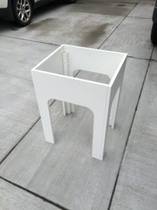
I worked on both the stand and printer in parallel, but I’ll discuss the stand first. Right away, I decided to postpone making a full enclosure for the printer (as I originally had sketched) and focus on the base, in the interest of time. The base is made of 3/4″ melamine panels (like are used to make shelves), with lengths of 2×2 board supporting each corner. I cut the panels using a circular skilsaw for the long cuts and a jigsaw for the fillets. It was somewhat of a challenge to bolt everything together, as I wanted to maintain the finish on all outside surfaces (to achieve a clean and smooth appearance for aesthetic purposes). Thus, I actually grinded down bolts to a length that wouldn’t protrude through the panel, and bolted everything together from the inside.
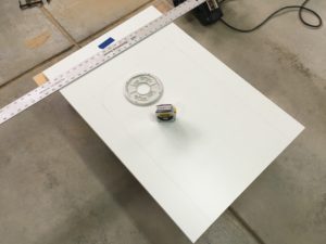
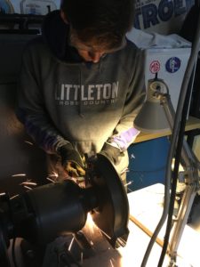
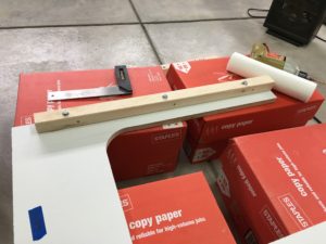
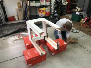
Once everything was bolted together, I applied edge tape to all of the unfinished edges to make everything white. One of the difficulties with using melamine is that it chips very easily, so I also when around the edges with white paint and a small brush and touched up the areas that were chipped. I’m actually very pleased with how it turned out.
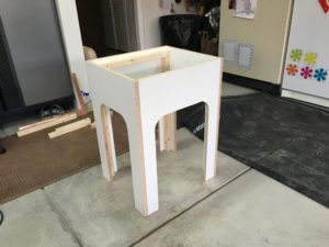
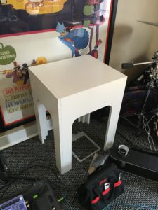
The final aspect of the base was the plate which the printer actually sits on. Also made of 3/4″ melamine sheet, it slips inside of the four side panels, supported by horizontal 2×2 boards glued into place. It is not fastened to the stand, so that I can remove the entire printer assembly (and its baseplate) if I want to work on it someplace else while not on the entire stand. This also allows me to secure the power supply unit (PSU), controller, and excess harnessing underneath the panel and everything can travel as one unit. I haven’t yet mounted these components to the underside of the panel, but when I do I will also attach four mini “legs” (also made of 2×2 board) to the underside so that the assembly can sit on these legs when not installed in the stand itself (and not sit on the electrical components themselves).
Designing the Printer
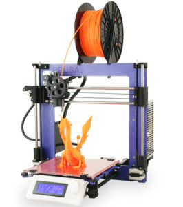
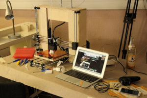
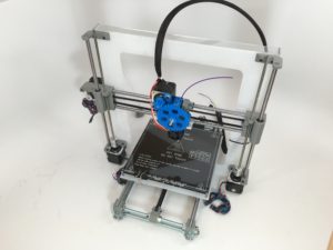
While 3D printers aren’t incredibly complex, I decided to closely follow the design of the RepRap Prusa i3 (above), which is a rather attractive design to start with. Most of the components of this printer are 3D printed (these printers are considered “self-replicating”), and the files can be found online at resources like reprap.org. Luckily, this meant I didn’t have to worry about the mechanical design of many components. Unfortunately, the were in either a .stl format (read by a 3D printing program) or a .scad format (created and edited with an open-source, coding-based program called OpenSCAD, which I couldn’t use very well and didn’t want to learn). For this reason, I decided not to make a full CAD model of the entire printer assembly so I didn’t have to re-design every component myself. This was pretty challenging, as as a mechanical engineering student I’m very accustomed to having every component perfectly modeled up. Instead, I needed to be better about double-checking sizes of things myself, and thinking through all of the parts that I was purchasing or printing.
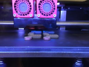
I did modify some components to fit my design better and help size the surface area required for the stand. Some of my modifications include adding little “feet” to the corners of the Y-stage, which holds the build plate. I envisioned bolting these to the stand for better stability. Additionally, I had to redesign the parts which interface with the belts, as the belt I was using (GT2) seems to be a different size than the builders who posted the original part files use. This was a pretty fun thing to redesign, as I needed to find the spec for GT2 belt teeth, and design mating features accordingly. The best part: it worked.
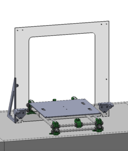
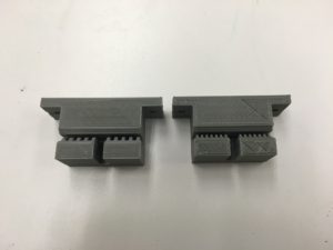
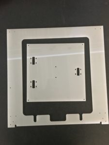
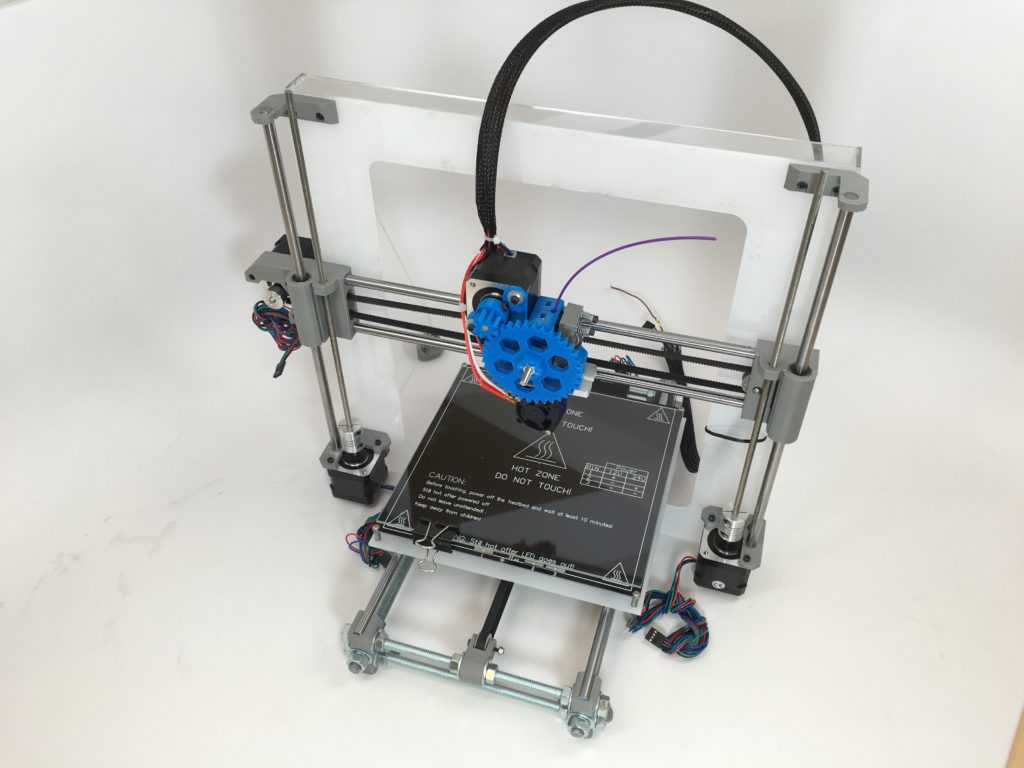
I did have a hand in material and component selection for this project. For one, I could choose the color of my 3D printed parts based on the colors I had available to me. I went with gray for most of the parts I printed, because I think it is very neutral and doesn’t call much attention to all of the components. Additionally, I needed to choose what I would make the frame of the printer with. Most Prusa i3’s are made with either a aluminum frame (~.25″ thick, as seen in the image above with a purple frame) or a laser-cut wooden box frame (the other image above). I prefer the look of the flat sheet frame, but didn’t want to buy a large piece of aluminum (~$50). My answer was nearly found when I got a piece of frosted white acrylic from the now-eliminated scrap pile at McGuckins for $3. I therefore planned to make both the frame and the build plate structure (not the build plate itself, which is made of glass) from this piece.
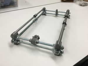
Regarding hardware, I had some choice on rod sizes which determined the size/type of fasteners and bearings I would use. Surprisingly, the DIY 3D printing world seems to use metric fastener sizes almost exclusively. Unfortunately, metric sized hardware can be more difficult to find and often more expensive, which I found especially with the threaded rods. At the same time, many parts often used in 3D printers were much easier to find in metric sizes, and nearly impossible to find in imperial sizes for reasonable prices (like the linear bearings). Additionally, metric fasteners have generally smaller outer dimensions, which meant that they aren’t really interchangeable in the parts that have either counterbores or press-fit cavities for nuts. For these reasons I ultimately decided to use both metric and imperial hardware where appropriate. The threaded rods which comprise the y-axis base are 3/8-16 and 5/16-18 threads (instead of M10 and M8 sizes, respectively) picked up from McGuckens, while the smooth rods on each axis are 8mm precision rods that I had to order from Alexandria Precision (who charged me double what was quoted for shipping). The threaded “lead screw” rods for the z axis are M5 thread, which I had to also order online.
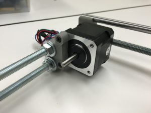
Finally, I had a bit of flexibility in choosing the components which make the printer itself work: motors, bearings, build plate, electronics, and extruder. I found a good deal on decent stepper motors on Amazon (5 NEMA 17 motors for $62 total), which actually have a bit more torque than many motors used for these projects. Plus, these motors were all black, which I thought was more aesthetically pleasing than the more common mixed-color varieties. For bearings, there are four different types used throughout the printer and I generally went with the cheapest that I could find that still had good reviews (again on Amazon). I spent ~$50 on bearings. For the build plate, I got an Mk2 etched heatbed ($18), and tempered glass build plate ($14) which should both make for nice print adhesion when I get this thing working. I like the Mk2 heatbed because it is black, which is much better looking than the standard red heatbeds (for this project at least). For the electronics, I decided to go with a RAMPS controller widely used in RepRap projects. It is basically a fancy shield for an Arduino Mega. I found a cheap Chinese kit on Amazon which came with an Arduino Mega, the RAMPS shield, an LCD screen, and five stepper motor drivers (all for $38). This is all powered by a 12V 30A power supply unit, also found on Amazon ($24). I didn’t decide on an extruder until later on in the process, so it will be discussed in a subsequent section.
With these decisions for materials, components, and fasteners made, I began construction.
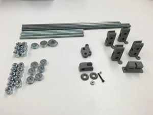
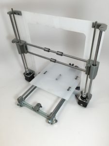
At this point, the printer’s three axes had been effectively built up on the frame, but the entire thing wobbled like crazy as the frame was only clamped at the bottom by two bolts on the Y-stage. To secure the frame I designed a gusset system using a piece of clear acrylic that I purchased from McGuckens. I simply laser cut two triangular pieces for the sides and a rectangular piece to go across the top for stiffness, along with two 3D printed brackets which I could bolt to both the stand and the gussets. I really liked how the clear gussets look, because they aren’t very obvious from across the room, and they hardly show up in any pictures. When I finally bolted to the baseplate, the printer was really solid and hardly rattles at all when I shake it around.
Extruder
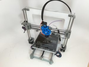
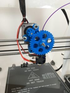
The extruder setup I’m using is the basic design published for Prusa i3 builds, using a stepper motor with a reduction gear system that drives a shaft to pull the filament through. Extruders are separated into hot ends (the part with the heating element and nozzle) and cold ends (everything that shouldn’t get hot). I purchased a cheap hot end setup on Amazon ($21), which included a heating element, heatsink, fan, and thermocouple. I 3D printed almost all of the parts for the cold end (besides the shaft, bearings, and a neat hobbed extruder gear which engages the filament). The hot end attaches to the cold end via a mounting bracket, which I also purchased (figured it was easier to pay $8 than machine a piece of aluminum). As luck would have it, the bracket turned out not to have holes in the right places so I had to modify it on the mill anyway.
For the 3D printed parts of the extruder, I decided to print them in a vibrant blue color so that they stand out a bit more and you can see them moving. By making them blue with a predominantly white background, I think my project really took on more of a “post-modern” aesthetic. Of course, I can print a new component anytime I please of any other color if I change my mind.
Electronics and Wiring
As previously mentioned, I’m using a RAMPS 1.4 setup (running off an Arduino Mega), with a knock-off “RepRapDiscount Full Graphic Smart Controller” LCD screen (included in the kit). I have a large 12V 30A PSU to power the printer, because the motors suck quite a bit of current. I think that electronics and their accompanying wiring is pretty ugly, so I decided to mount all of this underneath the printer baseplate with only the LCD screen showing. This is definitely an improvement on the other projects and kits that I’ve seen, which mount the electronics either in plain sight or in enclosures sitting right behind the frame. I drilled holes in the baseplate for the stepper motor wires and extruder hot end controls to pass through (one hole underneath the left Z axis stepper motor, and one in the inside corner or the right gusset). I passed all of the wires going to the extruder block through a black braided wire sleeve, which actually contains everything quite well. This harness continues through the rightmost hole, to the electronics below.
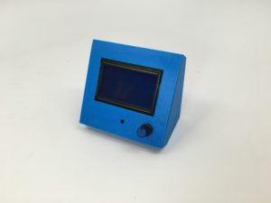
Finally, I needed to mount the LCD screen in an easily accessible location which also provides access to an SD card slot behind the screen. The easiest option was to design and 3D print an enclosure, which I decided to do with blue filament. This matches the extruder, and continues the post-modern aesthetic.
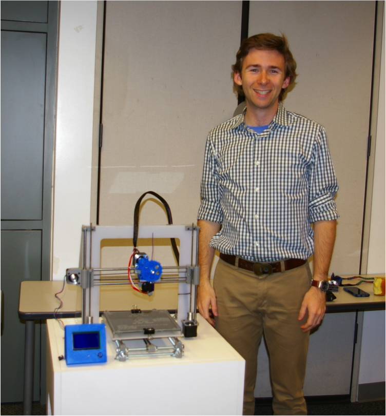
I’m really pleased with how clean the printer looks with all of the harnessing managed and hidden underneath the stand, with the control screen off to one side.

“Completed” Project
This project is certainly not completed, and I hope to finish up once the semester ends and I have more time. At this point, all the mechanical components are in place and the electronics need to just be troubleshooted and calibrated. I expect to spend about 20 more hours on this project before I’m making my first prints! In the meantime, I’ll be enjoying the view of this aesthetically designed printer and stand, which now sit in my living room.

6 Comments. Leave new
Really awesome work!! The product you had as of the expo looks super polished, even if its not at 100% yet. Would love to see it once it’s fully functional.
Chip, I think this project came out great. The stand really adds a lot to it and the addition of the blue printed parts is cool. I think an enclosure is definitely a good idea. 20 hours of calibration doesn’t sound like much fun to me but I bet it flies by. Good work man!
Chip, your printer and stand are awesome. I can totally imagine it being right at home in a living room, even without the cover. I think what you have accomplished is great and if you do make a cover and filtration system it will be even more at home in a domestic setting. Perhaps you could use it to somehow 3D print a modular case for itself?
Even though you didn’t “complete” the project, I think that we all know how much time and energy you put into this project. It looks great so far. At the expo, I overheard Professor Reuben discussing a rotating ability. Were you originally planning on doing that to hide the component when not in use? Like you were saying that would probably be a step that would be very difficult. Are you planning on giving it a cover instead, or do you like having the components exposed?
I’m headed toward making an enclosure for it, hopefully with a fan and filter so I can vent everything outside.
Seeing this at expo, the finished product looks very attractive. I liked the way you built the frame/ support for the machinery too. I think it would’ve been interesting to continue the clean white structure/ cover over the printing mechanisms to completely cover the mechanical stuff.