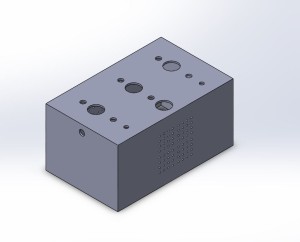
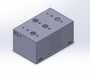
With the senior design pre-expo next week I have not been able to get as much done with this project as I had hoped. I worked a little on the code, the circuitry, and the CAD and I bought a few more parts. Below is the CAD of the orb’s control panel.

This view shows the top, left side, and front of the panel. The top has holes for the buttons, potentiometers, and LEDs that will turn on to indicate the button/potentiometer has been turned on. The single hole on the left side is for the sound detector and the multiple holes on the front are for air flow.

This view shows the top, right side, and back side of the panel. The right side will have an op/off switch for the entire system with an LED indicator. The back has 2 rectangular cutouts for the usb power cord and for the wires that go to the orb. On the inside of this face I will mount a computer fan that will cool the arduino and circuit that will be inside the box.
The plan is to laser cut each side out of a black polycarbonate sheet.

1 Comment. Leave new
Looks like you’ve got most of everything figured out in terms of the components of your project and how they will play into the main LED action. How do you plan on getting a sound detector to work in terms of controlling the motion/rotation of the orb? I like the idea of using the black polycarbonate material for your control box, since its simple and sleek. Did you think about incorporating more of an aesthetic in the design of the box, or did you want it to remain as a background item for the orb? I’m not thinking a lot of detail, but maybe some rounded corners? Some etching? Perhaps your name or a personal logo. Good luck continuing with everything!