I spent a fair amount of time working on this project over the break. I currently have both amplifier circuits wired and functioning with an input from the waveform generator so we are off to a good start.
Pre-Amplifier
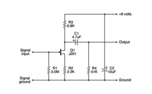
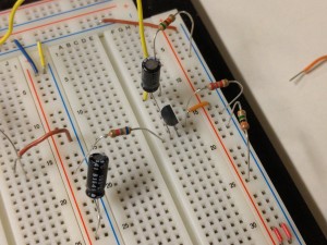
For the pre-amplifier I simply copied a popular design seen a lot in guitar forums originally created by Donald Tillman. The circuit diagram can be seen below. It uses a JFET as the amplifier as this type of transistor “warms” the sound in a way similar to traditional guitar amps. This was actually a fairly difficult to find component as the one this circuit is designed around has been out of production for some time. Luckily I was able to acquire some from my home state of Oklahoma via Mammoth Electronics. The rest of the components were easy to find on Digikey which is my go to source for electronic components due to their vast inventory. Assembling and testing the circuit showed it to be successful although with less amplification, or gain, than I was expecting.
Power Amplifier
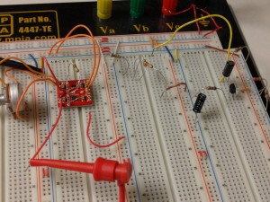
For the power amplifier, rather than building my own, I will be using Sparkfun’s audio amplifier breakout board. This board is a self contained audio amplifier and even allows for the addition of a potentiometer for volume control. Wiring this little breakout was super simple and was quickly tested and integrated with the pre-amp. The one issue with integrating the two circuits together was the power supply voltage. The pre-amp requires a 9 V power supply while the power amp operates on power from 2.5 V-5.5 V. Since both will be housed in the guitar it is important that they both run from the same power supply. The obvious solution is to use a voltage divider but I had difficulty measuring the resistance of the breakout board as it varied based on the input and the potentiometer setting. Through a bit of trial and error I was able to find that a 270 Ohm resistor dropped the voltage to within the operable range for all cases. Once this was accomplished I was even able to get the speaker hooked up and producing sound!
The Guitar
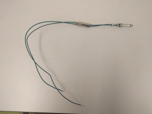
I obviously want to make sure that the electronics can sufficiently amplify the guitar’s signal before I begin cutting the guitar and putting the circuitry inside. To do this I need a way to send the signal to the breadboard. I bought some 1/4″ audio jacks (standard size for instrument and speaker cables) and soldered some wires to them as seen below. This allows me to plug the jack into the guitar and plug the wires into the breadboard. Testing this component showed that the signal was being transmitted but also that the signal was had a much smaller amplitude than expected. While, the webpage linked above for the pre-amp states that the signal coming from the guitar’s pickups can be up to 2 V peak to peak; I found my guitar to be outputting something closer to 400 mVpp. This is a huge difference and sort of invalidates my previous speaker testing as I had the waveform generator set to output at 2 Vpp. Despite this I went ahead and plugged the guitar in. I was getting a decent signal out of the pre amplifier but the output of the power amplifier was simply noise. The noise was at 10 Vpp which I am currently looking at as a good thing since it means there is a decent amount of amplification happening.
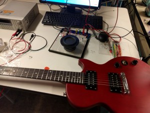
So this is about where I am at right now. The guitar signal amplitude has set me back from my planned schedule by about a week but I had included a decent amount of buffer at the end so I should be OK. While I sort this out I plan to get the design for the cutouts that I need to add to the guitar mostly sorted so that I continue moving forward.

1 Comment. Leave new
This idea is great. It seems that you are troubleshooting your way through the electronics. I wonder what aesthetics you could incorporate along with the basic function of the electronics. There’s so many awesome inspirations out there for the integration of musical things and art. Perhaps, the guitar body where the speaker is housed can be designed towards creating an interesting effect–maybe use the aesthetic game as an exercise for generating ideas of combined aesthetics. Also, reminds me of some other really cool homemade instruments I’ve seen. Consider looking into these for further design inspirations. Great job