For my main project, I would like to build a mechanical clock that functions primarily as an aesthetic expression and secondarily as a time-telling device. Originally, mechanical clocks functioned as an important tool to measure time. However, due to the proliferation of inexpensive quartz clocks, computers and cellphones mechanical clocks are too inaccurate (+/- 15 seconds per day) and inconvenient to be competitive. However, I think mechanical clocks have an expressive quality often lacking in digital devices. I believe this aesthetic comes partially from the visual nature of the mechanism. In digital devices, the timekeeping quartz oscillator is hidden and resonates imperceptibly.
I would like to build a clock that has a pleasing minimalist design aesthetic and illuminates it’s mechanism of action rather than obscuring it. A minimalist aesthetic will serve this goal because it aims to strip away all of the unnecessary parts of a design. In many mechanical clocks, for space saving reasons or to communicate complexity, components are crammed into a tight space. This obscures the relationships between the parts and overwhelms the viewer. In contrast, my design will spread components out so their function may be more readily understood. My hope is that the first impression that the device provokes is “I see how that works” rather than “That thing is really complicated”.
In terms of function, the clock will tell give the general impression of the time but won’t attempt to be a precise device. I plan to accomplish this by eliminating the clock face and only using a single signifying mark for the 12 o’clock hour. Ideally, the object will act as a kinetic sculpture grounded in the tradition of historic mechanical clocks.
My inspirations for this project were the more abstract clocks available for purchase and the wooden clocks made by the woodworking community. The abstract clocks shown below have a clean minimalist design, but they obscure the inter-workings of the device. My design will add a new dimension to the minimalist aesthetic by showing the simple mathematical relationships between the different components in an easily digestible way.
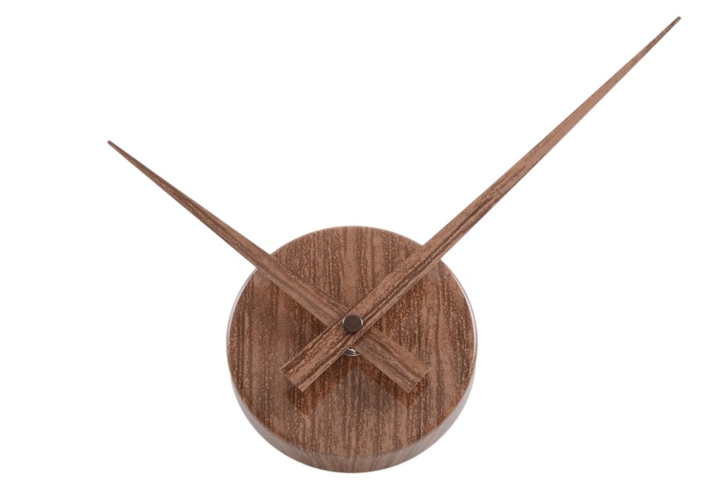


I really admire the work of the mechanical clockmakers in the woodworking community, but I’ve found that their creations are focused on increasing complexity. Typically, designs highlight the technical skill and ingenuity of the designer. This is a worthy goal, but I would like my design to be easily understood and interesting to a non-engineer.
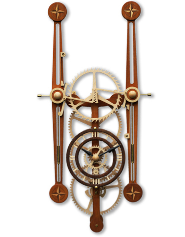
Sextus by David Atkinson @ Woodentimes
Journey Clock by Clayton Boyer
For my design, the critical component will likely be the escapement mechanism. I have chosen to use a deadbeat mechanism which is a variant of an anchor escapement. The anchor escapement was a significant advancement in clock-making because it was significantly more accurate than it’s predecessor the verge escapement.

Verge Escapement By AlienAtSystem – Own work, CC BY-SA 4.0

Anchor Escapment By Chetvorno – Own work, CC0
The deadbeat anchor mechanism is easy to fabricate as compared to other escapement schemes. It is also it is one of the more accurate mechanical escapements even though that isn’t a major consideration in this project. In addition to the escapement, I am curious about incorporating a small motor to rewind the clock, so it doesn’t require any maintenance from week to week.
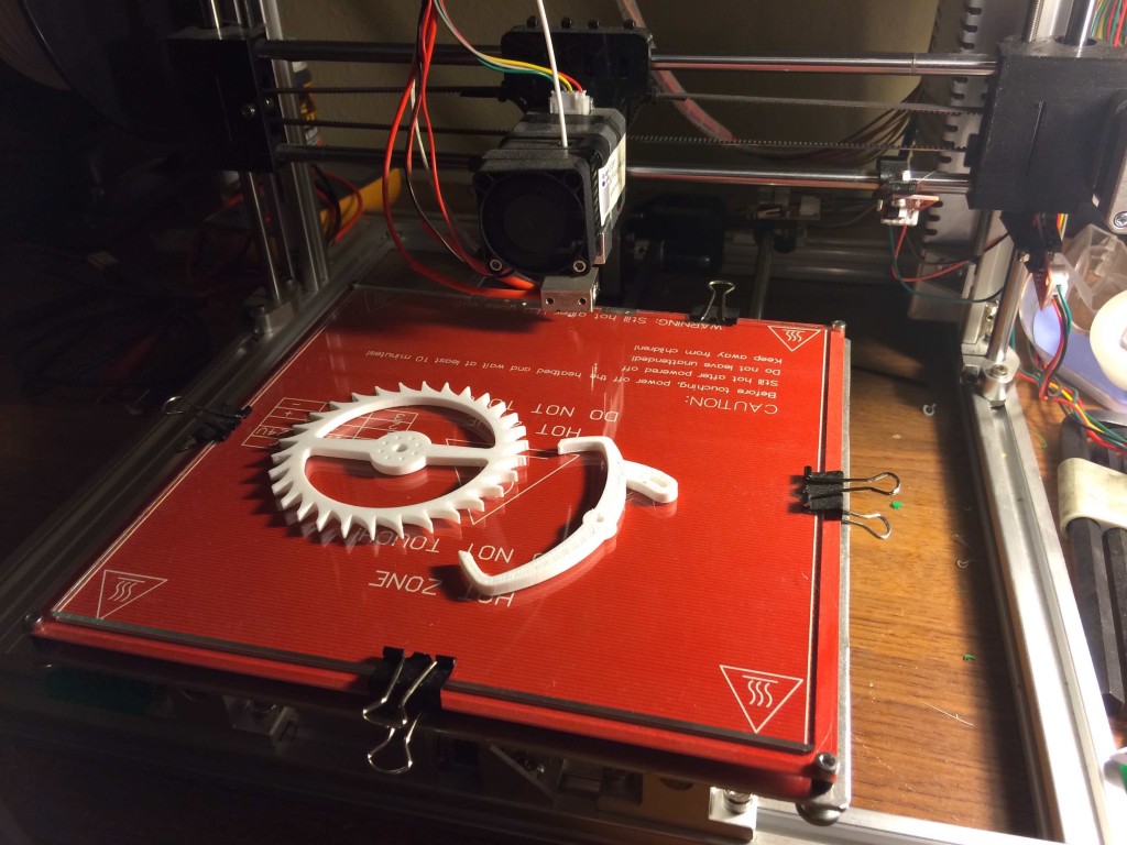
I’ve begun prototyping the deadbeat escapement by adapting design files developed thingiverse user “TheGoofy” and my homebuilt 3d printer. Right now I only have a few parts, but I will update this section to reflect my progress.
Project cost estimate:
The primary expense for my project will be sheet material used in the construction of the clock mechanism. I will either use lasercut 1/4″ white birch plywood or colored acrylic.
Plywood ~ $20 (24″ x 48″ sheet)
Acrylic ~ $50-$70 (24 x 48″ sheet)
Misc hardware ~$20
Optional components for motorized rewinding:
Estimated total cost >$150
Project timeline:
Design Review Presentation: March 4th
Develop working escapement mechanism: March 9th
Order high priority components: March 12th
Complete Design Calculations: March 12th
Complete CAD model with BOM: March 14th
Design Review & Revision: March 18th
Begin Fabrication: March 16th
Complete Fabrication: March 30th
Testing and report writing: April 1 – April 13th

6 Comments. Leave new
Haha! We’ve both got different takes on clocks going on for our projects.
Bonus points for using your own 3D printer, right?
I’m excited to see how yours turns out. Are you going to use the 3D printed material as the frictional contact surface on your gearset, or add metal contact zones to each? I have no idea what the wear or lifespan on the 3D printed parts would be, but could be an option if the frictional affects get to be too high for this material.
Oh wow, I really hope this works out! I have a lot of faith in it. What kind of image do you want to evoke?
Absolutely love this idea, especially how it is entirely mechanical and non-electronic. I’m excited to see the final result and what design you end up with!
this is a great idea. I like the mechanical component to it.
Great Idea, I have a similar fascination with mechanical actuation (vs. those cheap chinese clock mechanisms), so I’m really into the actual oscillator driven clock.
I like the idea of having the components separated so you can see how it all works. I’m excited to see if it all fits together!